
RF output power closed-loop detection and adjustment device

A power closed-loop and regulating device technology, which is applied in the microwave and radio frequency fields, can solve the problems of power amplifier influence, radio frequency signal distortion, communication failure, etc., and achieve the effect of precise power control and low noise control level

Inactive Publication Date: 2018-11-30
CHENGDU JIUZHOU ELECTRONIC INFORMATION SYSTEM CO LTD
View PDF15 Cites 3 Cited by
  • Summary
  • Abstract
  • Description
  • Claims
  • Application Information

AI Technical Summary

Problems solved by technology

[0003] At present, most of the output power control is realized by sampling feedback and DAC output control level. The main problem is that the ladder and noise of the DAC output signal will have a great impact on the sensitive power amplifier, and even cause the radio frequency signal. Distortion affects the normal communication of the system to a large extent, and even directly causes communication failure

Method used


Image

  • RF output power closed-loop detection and adjustment device
  • RF output power closed-loop detection and adjustment device
  • RF output power closed-loop detection and adjustment device

Examples


Embodiment 1

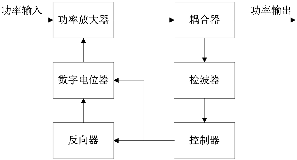
[0031] On the basis of the above closed-loop detection and adjustment device for radio frequency output power, the present invention further details the power amplifier, coupler, detector, controller, digital potentiometer and inverter.

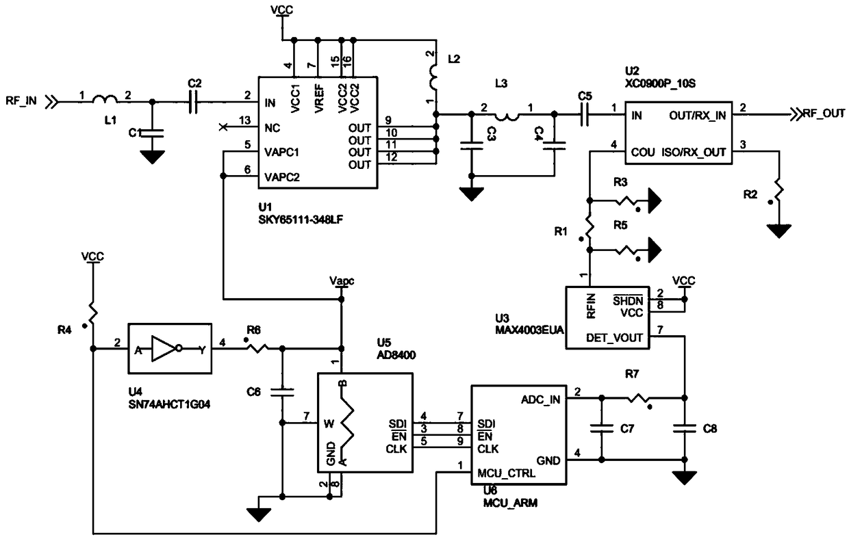
[0032] Such as figure 2Shown is a schematic diagram of the circuit structure of Embodiment 1 of the present invention. Power amplifier U1 of the present invention adopts SKY65111-348LF chip, and its pin 2 (IN end) enters the system input power RF_IN through the input matching network, and pin 5 (VAPC1 end) and pin 6 (VAPC2 end) are all connected to the gain control circuit Flat (Vapc terminal) connection, pin 4 (VCC1 terminal), pin 7 (VREF terminal), pin 15 (VCC2 terminal), pin 16 (VCC2 terminal) are amplifier power input pins, connected to external voltage VCC, Pin 9 (OUT), Pin 10 (OUT), Pin 11 (OUT), and Pin 12 (OUT) output power to the coupler U2 through the output matching network, and connect to the external through the second inductor...

Embodiment 2

[0039] On the basis of the above closed-loop detection and adjustment device for radio frequency output power, the present invention further elaborates its application extension.

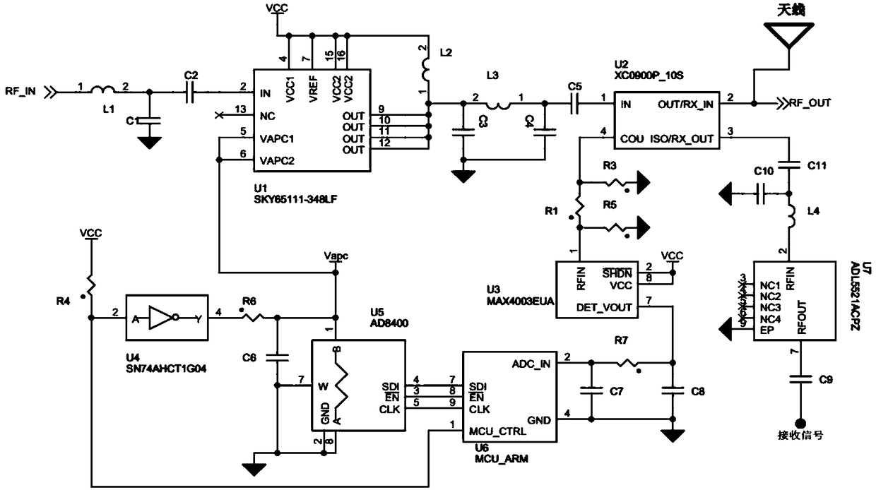
[0040] Such as image 3 Shown is a schematic diagram of the circuit structure of Embodiment 2 of the present invention. The radio frequency output power closed-loop detection and adjustment device of the present invention also includes an antenna; the antenna is connected to the pin 2 of the coupler.

[0041] The RF output power closed-loop detection and adjustment device of the present invention also includes a low-noise amplifier U7; the low-noise amplifier U7 adopts the ADL5521ACPZ chip, and its pin 2 (RFIN end) is connected with the pin of the coupler U2 through an input filter matching network. 3 connection, the pin 7 (RFOUT terminal) receives the signal through the ninth capacitor C9 input, and the pin 9 (EP terminal) is grounded; the input filter matching network includes the tenth capacitor...


PUM


Abstract

The invention discloses an RF output power closed-loop detection and adjustment device. The device comprises a power amplifier, a coupler, a detector, a controller and a digital potentiometer. The output end of the power amplifier outputs the power subjected to gain amplification to the coupler. The output end of the coupler directly outputs the output power of the power amplifier, meanwhile couples a part of the RF power to a coupling port, and outputs the power to the detector. The output end of the detector outputs an analog level value to the controller, the output end of the controller outputs a control signal to the digital potentiometer, and the output end of the digital potentiometer is connected to a gain control level input port of the power amplifier. The detector can obtain thereal-time output power of the system, and adjust the voltage divider resistance of the digital potentiometer through the controller to achieve the purpose of adjusting the Vapc. Under the premise that the RF input power is constant, the output power of the power amplifier U1 also changes accordingly to achieve detection and automatic adjustment of the system output power.

Description

technical field [0001] The invention belongs to the technical field of radio frequency and microwave, and in particular relates to a closed-loop detection and adjustment device of radio frequency output power. Background technique [0002] With the wide and in-depth application of radio frequency and wireless technology, radio frequency and microwave technology are widely used, and radio frequency and microwave power amplifiers are ubiquitous, and are used in almost all wireless communication modules, equipment, and terminals. It has a wide range of applications, such as radar, communication base stations, navigation systems, satellite ground stations, and various electronic countermeasure equipment; on the other hand, excessive output power will violate national standards, interfere with other communication equipment, and cause personal injury; Too small output power will cause communication failure. Furthermore, in many real-time communication systems, most of the output ...

Claims


Application Information

Patent Timeline
IPC IPC(8): H03F3/20H04B1/40G01R21/00
CPCG01R21/00H03F3/20H04B1/40
Inventor 王基石胡天军阚能华
Owner CHENGDU JIUZHOU ELECTRONIC INFORMATION SYSTEM CO LTD
Learn More