Clamp for carrying monocrystalline silicon rod
A single crystal silicon rod and fixture technology, which is applied in the direction of transportation and packaging, conveyor objects, etc., can solve the problem of low positioning strength of silicon rods, achieve good versatility, improve stability, and facilitate replacement
- Summary
- Abstract
- Description
- Claims
- Application Information
AI Technical Summary
Problems solved by technology
Method used
Image
Examples
Embodiment 1
[0044] Fixtures for handling monocrystalline silicon rods, used for moving or transferring single crystal silicon rods, or moving or transferring other columnar materials.
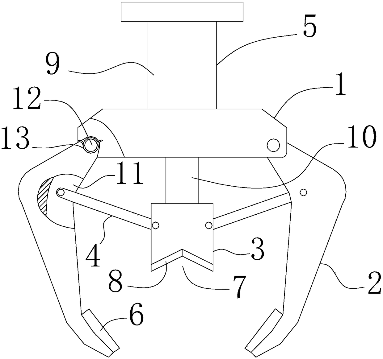
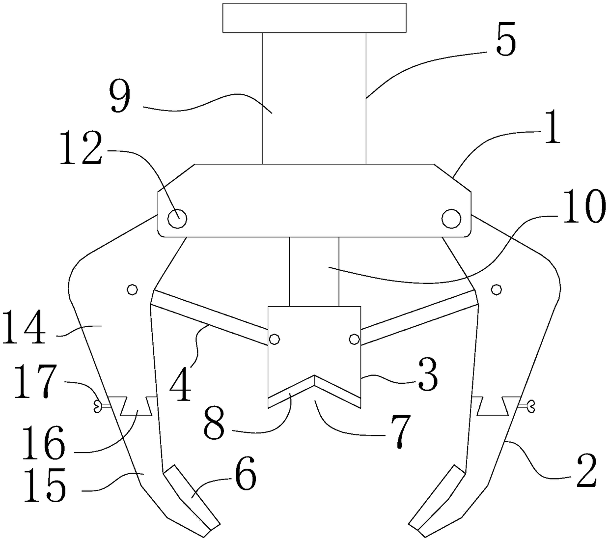
[0045] Such as figure 1 , the fixture includes a mounting base 1, and a clamping arm 2 is rotatably connected to the mounting base 1. There are two clamping arms 2, and the two clamping arms 2 are symmetrically arranged so that the two clamping arms 2 clamp the object to be clamped. .
[0046] Such as figure 1 , a pressing block 3 is also provided on the mounting seat 1, the pressing block 3 is located between the clamp arms 2, and the pressing block 3 reciprocates in a direction approaching and away from the mounting seat 1 .
[0047] Such as figure 1 A connecting rod 4 is arranged between the clamp arm 2 and the pressing block 3, one end of the connecting rod 4 is rotatably connected to the clamp arm 2, and the other end of the connecting rod 4 is rotatably connected to the On the pressing block 3, ...
Embodiment 2
[0052] This embodiment is an optimized solution for the clamp arm 2, which can be combined with Embodiment 1.
[0053] Such as figure 1 , the clamp arm 2 is provided with a buffer sheet 6, the buffer sheet 6 is arranged at the end of the clamp arm 2 away from the mounting base 1, and the buffer sheet 6 is provided with an enlarged buffer sheet 6 patterns of friction coefficient. The buffer sheet 6 is in contact with the clamped object, and clamps the clamped object.
[0054] The buffer sheet 6 can be made of rubber material, or other soft materials, so as to prevent the buffer sheet 6 from damaging the clamped object.
[0055] The buffer sheet 6 is adhered to the clamp arm 2 . The buffer piece 6 can also be fixed on the clip arm 2 by other means.
Embodiment 3
[0057] This embodiment introduces the compression block 3, which can be combined with Embodiment 1 or Embodiment 2.
[0058] Such as figure 1 , The pressing block 3 is provided with a V-shaped groove 7, and the V-shaped groove 7 is arranged on the side of the pressing block 3 in contact with the object to be clamped.
[0059] The function of the V-shaped groove 7 will be specifically introduced below through the shape of the clamped object.
[0060] Such as Figure 4 , when the clamped object is cylindrical, the side wall of the V-shaped groove 7 is in contact with the side wall of the clamped object to position the clamped object, and cooperate with the clamp arm 2 to realize three-point positioning of the clamped object.
[0061] Such as Figure 5 , when the shape of the object to be clamped is prismatic, one edge of the object to be clamped cooperates with the V-shaped groove 7, that is, a part of a ridge line of the object to be clamped is located in the V-shaped groove...
PUM
 Abstract
Description
Claims
Application Information
 - Generate Ideas
- Intellectual Property
- Life Sciences
- Materials
- Tech Scout
- Unparalleled Data Quality
- Higher Quality Content
- 60% Fewer Hallucinations
Browse by: Latest US Patents, China's latest patents, Technical Efficacy Thesaurus, Application Domain, Technology Topic, Popular Technical Reports.
© 2025 PatSnap. All rights reserved.Legal|Privacy policy|Modern Slavery Act Transparency Statement|Sitemap|About US| Contact US: help@patsnap.com


