Steel plate punching welding device

A technology of stamping and welding, steel plate, applied in the direction of stripping device, feeding device, storage device, etc., can solve the problem of workpiece damage, unable to realize continuous material loading, etc., achieve accurate rotation angle, is conducive to stable blanking, and adjustable speed Effect

Inactive Publication Date: 2018-11-27
赵锋
View PDF0 Cites 2 Cited by
  • Summary
  • Abstract
  • Description
  • Claims
  • Application Information

AI Technical Summary

Problems solved by technology

At present, the common material receiving boxes are generally fixed. Once the stamped parts are stuck on the material receiving box, it will cause damage to the workpiece and cannot continue to carry materials.

Method used


Image

  • Steel plate punching welding device
  • Steel plate punching welding device
  • Steel plate punching welding device

Examples


Embodiment Construction

[0016] The present invention will be further described in detail below in conjunction with the accompanying drawings and examples. The following examples are explanations of the present invention and the present invention is not limited to the following examples.

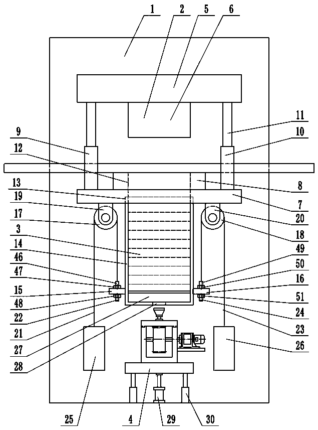
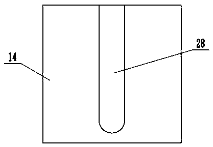
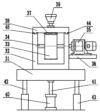
[0017] Such as figure 1 , figure 2 , image 3 and Figure 4As shown, a steel plate stamping and welding device includes a frame 1, a stamping mechanism 2, a material receiving mechanism 3, and a blanking mechanism 4. The stamping mechanism 2 includes an upper stamping support 5, an upper stamping die 6, a lower stamping support Seat 7, lower stamping die 8, stamping driving cylinder 9, the lower stamping support 7 is fixed on the frame 1, the lower stamping die 8 is installed on the upper end of the lower stamping support 7, the stamping driving cylinder 9 includes stamping Cylinder 10 and stamping piston rod 11, the stamping cylinder 10 is fixed on the lower stamping support 7, the upper end of the stamping pis...


PUM


Abstract

The invention provides a steel plate stamping welding device, and belongs to the technical field of mechanical processing. The device comprises a punching mechanism, a material bearing mechanism and ablanking mechanism, a lower punching die of the punching mechanism is installed at the upper end of a lower punching support seat, an upper punching die is installed at the lower end of an upper punching support seat, a blanking slot is formed in the lower end of the front side of a material bearing box of the material bearing mechanism, a U-shaped blanking groove is formed in the lower side of the material bearing box, an opening faces the front side, the upper end of the material bearing box is inserted into a material bearing box slot of the lower punching support seat under the action ofa left gravity block and a right gravity block, a blanking sliding plate of the blanking mechanism can slide back and forth on a sliding groove of a gear box through a sliding block, a blanking gear and a blanking rack are meshed with each other, and a blanking sucking disc is mounted on the upper side of the blanking sliding plate. The device not only utilizes the floating material bearing box toachieve the material bearing of a workpiece after the stamping, and facilitates the smooth falling of the workpiece into the material bearing box, but also uses a gear rack structure to achieve the blanking one by one of the workpiece in the material bearing box.

Description

technical field [0001] The invention relates to the technical field of mechanical processing, in particular to a steel plate stamping and welding device. Background technique [0002] Machining refers to the process of changing the shape or performance of a workpiece through a mechanical device. According to the difference in processing method, it can be divided into cutting processing and pressure processing. Cutting refers to the processing method of using cutting tools to cut off the excess material layer on the blank or workpiece into chips, so that the workpiece can obtain the specified geometric shape, size and surface quality. The technological characteristics of cutting processing are determined by the structure of the cutting tool and the relative motion between the cutting tool and the workpiece. According to process characteristics, cutting processing can generally be divided into: turning, milling, drilling, boring, reaming, planing, slotting, broaching, sawing...

Claims


Application Information

Patent Timeline
Patent Type & Authority Applications(China)
IPC IPC(8): B21D45/00B21D43/20
CPCB21D45/00B21D43/20
Inventor 赵锋
Owner 赵锋
Why Eureka
Try Eureka