Waste gas absorption treatment device for casting production

A technology of treatment device and waste gas, applied in gas treatment, dispersed particle filtration, membrane technology, etc., can solve the problems of operator's health hazards, air pollution, large physical strength, etc., achieve full and thorough absorption, promote absorption, and increase utilization rate Effect

Inactive Publication Date: 2018-11-23
潍坊市宝利丰机械科技有限公司
View PDF6 Cites 4 Cited by
  • Summary
  • Abstract
  • Description
  • Claims
  • Application Information

AI Technical Summary

Problems solved by technology

[0004] In actual production, it is necessary to dig out the refractory sand in the casting sand box first, put it into the mold shell, then backfill the refractory sand to the height of the casting port of the mold shell, and then use a bamboo stick to plug the surrounding of the mold shell tightly. Casting is carried out again. After the casting is completed, the refractory sand is removed manually, and then the shell is moved to the ground by driving or other lifting equipment. First, because the casting sand box of the buried shell is lower than the ground, the heavy refractory sand Digging out from the casting sand box in the bunker requires considerable physical effort and produces a lot of dust. Secondly, the liquid metal at a temperature of thousands of degrees will react with the mold shell to generate harmful gases such as carbon monoxide, sulfur dioxide and toluene. Harmful gas is naturally discharged into the foundry through the air outlet, which not only causes harm to the health of the operators, but also pollutes the atmosphere. Therefore, it is urgent to provide a waste gas absorption and treatment device for casting production to facilitate the casting process. Absorption treatment of waste gas

Method used


Image

  • Waste gas absorption treatment device for casting production
  • Waste gas absorption treatment device for casting production
  • Waste gas absorption treatment device for casting production

Examples


Embodiment Construction

[0020] Below in conjunction with specific embodiment, the technical scheme of this patent is described in further detail:

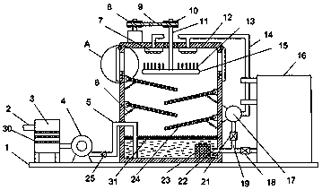
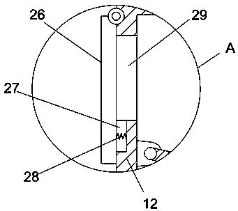
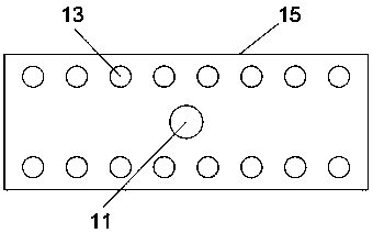
[0021] see Figure 1-3 , a waste gas absorption treatment device for casting production, comprising a bearing plate 1, an absorption box 12 is fixedly installed on the bearing plate 1, a driving motor is fixedly installed on the top of the absorption box 12, and the output shaft of the driving motor is fixedly installed coaxially There is a driving pulley 8, and the rotating shaft 11 is vertically arranged in the absorption box 12; the surface of the rotating shaft 11 is sleeved and fixedly installed with a driven pulley 10. The flat belt 9 is sleeved and connected; the lower end of the rotating shaft 11 is horizontally fixed with a rotating plate 15, and the upper surface of the rotating plate 15 is uniformly fixed with several vertically arranged dispersion rods 13, and the right side wall of the absorption box 12 is fixed. A water pump 17 is installed...


PUM


Abstract

The invention discloses a waste gas absorption treatment device for casting production. The waste gas absorption treatment device comprises a carrying plate, wherein an suction absorption box is fixedly arranged on the carrying plate; a driving motor is fixedly arranged on the top of the absorption box; a driven belt wheel is fixedly arranged on the surface of a rotating shaft in a sleeving manner; the outlet end of an air suction pump is communicated and provided with an air outlet pipe extending to the bottom of a liquid storage box; a discharging passage is formed in the upper side wall ofthe absorption box; a movable cover plate covered on the discharging passage is rotationally arranged on the absorption box. Through the swinging a plurality of installed swinging net plates, the baffling effect on the suction liquid can be realized; a scattering rod is driven to perform rotation scattering through the rotating plate; the refining of the suction liquid is promoted; the contact time between the suction liquid and waste gas is increased; the contact area between the waste gas and the suction liquid is also increased; the comprehensive and sufficient absorption of the suction liquid on the waste gas can be promoted; the cyclic spraying and supplementation of the suction liquid are realized, so that the utilization rate of the suction liquid is greatly improved; the waste gassuction is sufficient and thorough.

Description

technical field [0001] The invention relates to the technical field of waste gas treatment, in particular to a waste gas absorption and treatment device for casting production. Background technique [0002] Investment casting, also known as "lost wax casting", usually refers to making a pattern from a fusible material, coating several layers of refractory material on the surface of the pattern to make a shell, and then melting the pattern out of the shell to obtain a non-parting surface The casting mold can be filled with sand and poured after high-temperature roasting. Since patterns are widely made of waxy materials, investment casting is often referred to as "lost wax casting". The types of alloys that can be produced by investment casting include carbon steel, alloy steel, heat-resistant alloy, stainless steel, precision alloy, permanent magnet alloy, bearing alloy, copper alloy, aluminum alloy, titanium alloy and ductile iron. The shape of investment castings is gener...

Claims


Application Information

Patent Timeline
IPC IPC(8): B01D53/18B01D46/12
CPCB01D46/12B01D53/18B01D2257/93B01D2258/025
Inventor 郭河山
Owner 潍坊市宝利丰机械科技有限公司
Why Eureka
Try Eureka