Mask, manufacturing method thereof and exposure apparatus

Inactive Publication Date: 2016-10-13
BOE TECH GRP CO LTD +1
View PDF14 Cites 1 Cited by
  • Summary
  • Abstract
  • Description
  • Claims
  • Application Information

AI Technical Summary

Benefits of technology

The present invention provides a mask with two mask patterns, which reduces the size of the exposed region of photoresist compared to the light transmissive region of the mask, resulting in a finer pattern after development. The manufacturing method and exposure apparatus using this mask improve the process of patterning and facilitate further refinement.

Problems solved by technology

It can be seen that, the above mask cannot realize the refinement of an exposure process, and limits the accuracy of sizes of a thin film transistor and various signal lines in a display device, thus being unfavorable for improving a pixel density of the display device.

Method used


Image

  • Mask, manufacturing method thereof and exposure apparatus
  • Mask, manufacturing method thereof and exposure apparatus

Examples


first embodiment

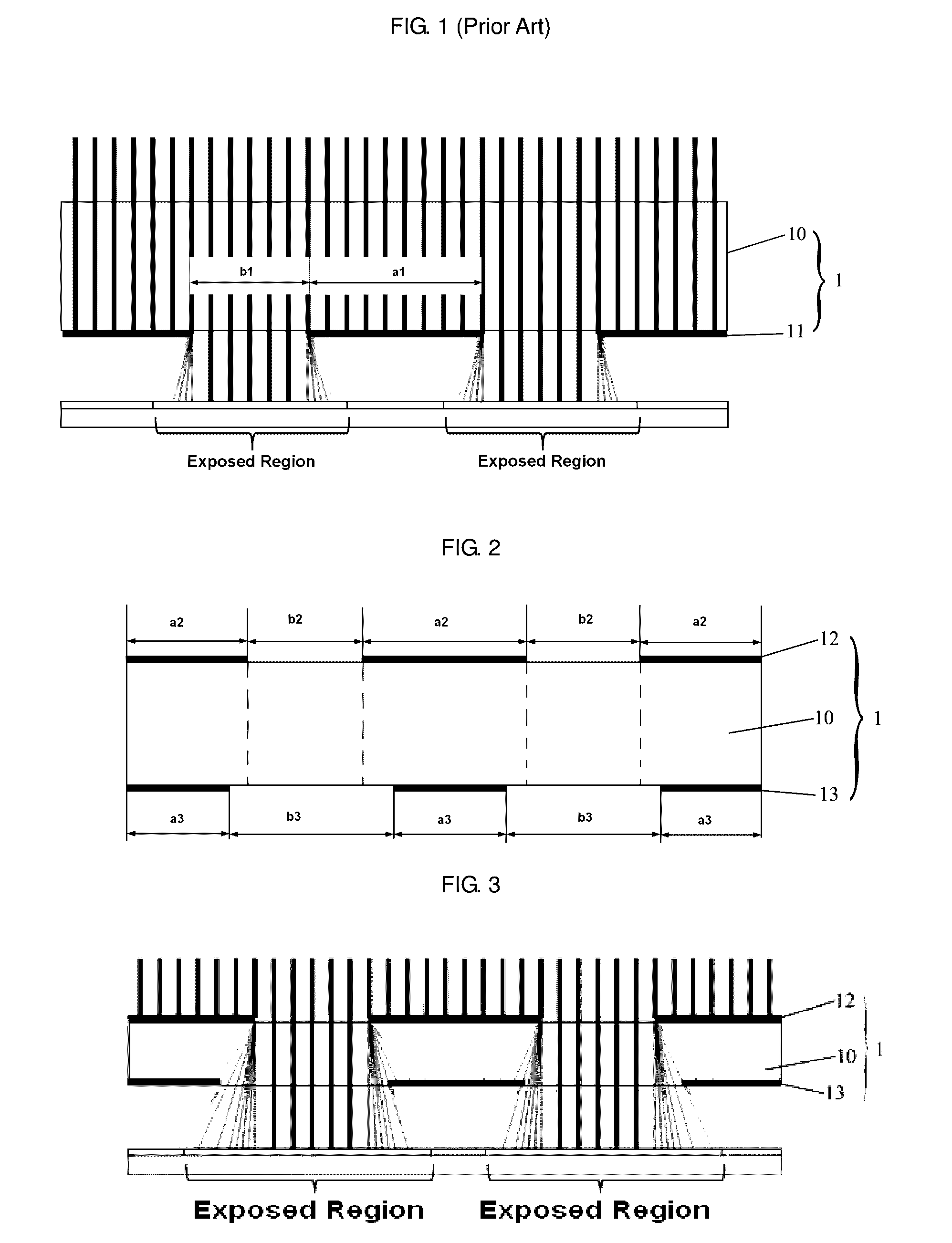
[0033]FIG. 2 is a schematic diagram of a mask provided by the present invention. As shown in FIG. 2, in the present embodiment, the mask 1 includes a base substrate 10, a first mask pattern 12 formed on an upper surface of the base substrate 10, and a second mask pattern 13 formed on a lower surface of the base substrate 10. In this case, it should be understood that, the lower surface of the base substrate 10 is an opposite surface opposite to the surface where the first mask pattern is located (i.e., the upper surface of the base substrate 10). The first mask pattern 12 includes light transmissive regions b2 and light blocking regions a2, and the second mask pattern 13 includes light transmissive regions b3 and light blocking regions a3. Further, a projection of each light transmissive region b2 of the first mask pattern 12 on a plane where the second mask pattern 13 is located is outside a corresponding light blocking region a3 of the second mask pattern 13, and within a correspo...

second embodiment

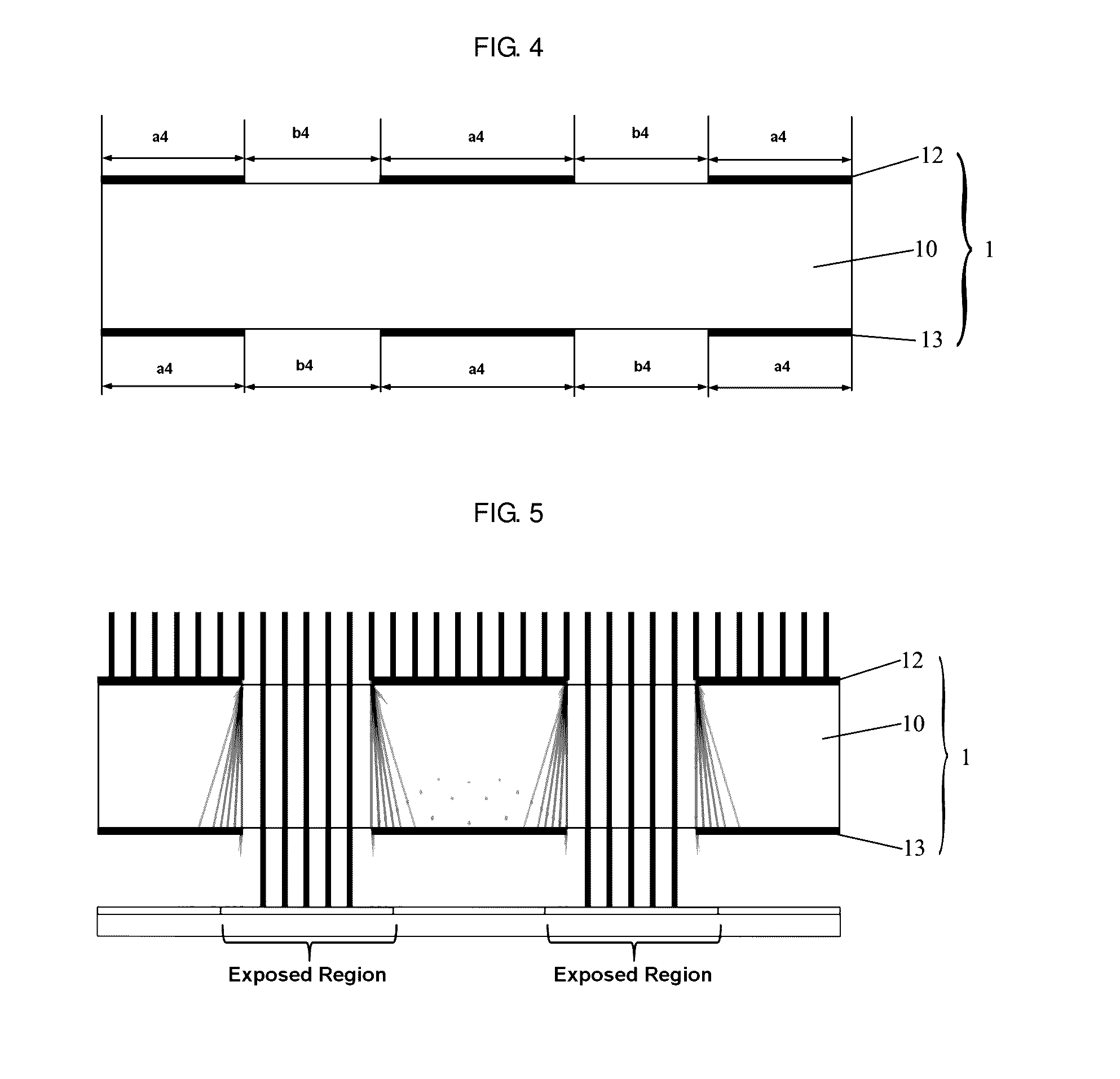
[0047]FIG. 4 is a schematic diagram of a mask provided by the present invention. As shown in FIG. 4, in the present embodiment, a mask 1 includes a base substrate 10, a first mask pattern 12 formed on an upper surface of the base substrate 10, and a second mask pattern 13 formed on a lower surface of the base substrate 10. In this case, it should be understood that, the lower surface of the base substrate 10 is an opposite surface opposite to a surface where the first mask pattern is located (i.e., the upper surface of the base substrate 10). The first mask pattern 12 includes light transmissive regions b4 and light blocking regions a4, and the second mask pattern 13 includes light transmissive regions b4 and light blocking regions a4. Further, a projection of the light transmissive region b4 of the first mask pattern 12 on a plane where the second mask pattern 13 is located is outside a corresponding light blocking region a4 of the second mask pattern 13, and coincides with a corre...


PUM


Abstract

The present invention provides a mask, comprising a base substrate, a first mask pattern formed on an upper surface of the base substrate, and a second mask pattern formed on a lower surface of the base substrate. Each of the first and second mask patterns comprises a light transmissive region and a light blocking region. A projection of the light transmissive region of the first mask pattern on a plane where the second mask pattern is located is outside the light blocking region of the second mask pattern, and the light blocking region of the second mask pattern can block at least part of light diffracted at a boundary between the light blocking region and the light transmissive region of the first mask pattern, to prevent the at least part of light from emitting from the light transmissive region of the second mask pattern.

Description

CROSS-REFERENCE TO RELATED APPLICATIONS[0001]The present application claims the priority of Chinese Patent Application No. 201510172699.4, filed on Apr. 13, 2015, the contents of which are incorporated herein in their entirety by reference.FIELD OF THE INVENTION[0002]The present invention relates to the field of display technology, and in particular, relates to a mask, a manufacturing method of the mask, and an exposure apparatus.BACKGROUND OF THE INVENTION[0003]In the field of display technology, structures, such as a thin film transistor, various signal lines, a pixel electrode, and the like, in a display device are manufactured by a photolithography process. The photolithography process generally includes steps of priming, coating a photoresist, exposing, developing, etching, stripping off the remaining photoresist, and the like, and among others, the step of exposing is performed by an exposure apparatus.[0004]FIG. 1 shows a mask used in an exposure apparatus in the prior art. A...

Claims


Application Information

Patent Timeline
IPC IPC(8): G03F1/50
CPCG03F1/50
Inventor WANG, MAN
Owner BOE TECH GRP CO LTD
Why Eureka
Try Eureka