
Device and method for recovery of waste heat from medium-and-high-temperature solid powder

A waste heat recovery device, medium and high temperature technology, applied in heat exchanger types, lighting and heating equipment, direct contact heat exchangers, etc., can solve the problems of wasting water resources, complex structure, air pollution, etc. Simple structure of pipes and devices, and the effect of improving heat exchange rate

Active Publication Date: 2018-11-16
NORTHEASTERN UNIV
View PDF8 Cites 0 Cited by
  • Summary
  • Abstract
  • Description
  • Claims
  • Application Information

AI Technical Summary

Problems solved by technology

A large amount of medium-high temperature powder is produced during the production process, and most of them are mixed with air to recycle the high-temperature air containing powder through convective heat exchange or directly discharge it into the atmosphere. Some enterprises also use traditional water cooling, which not only wastes water resources , also caused a large amount of heat loss, resulting in greatly reduced energy utilization efficiency, resulting in a large waste of energy
After being mixed with air, the high-temperature air containing powder is directly discharged into the atmosphere, causing serious air pollution
[0003] At present, the waste heat recovery device for medium and high temperature solid powder has a complex structure and high cost, and only a few large enterprises have equipped it, while small enterprises have no equipment due to insufficient funds and technology, resulting in a large amount of heat loss

Method used


Image

  • Device and method for recovery of waste heat from medium-and-high-temperature solid powder
  • Device and method for recovery of waste heat from medium-and-high-temperature solid powder
  • Device and method for recovery of waste heat from medium-and-high-temperature solid powder

Examples


Embodiment 1

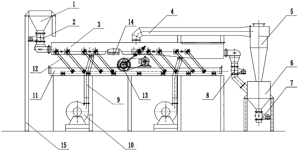
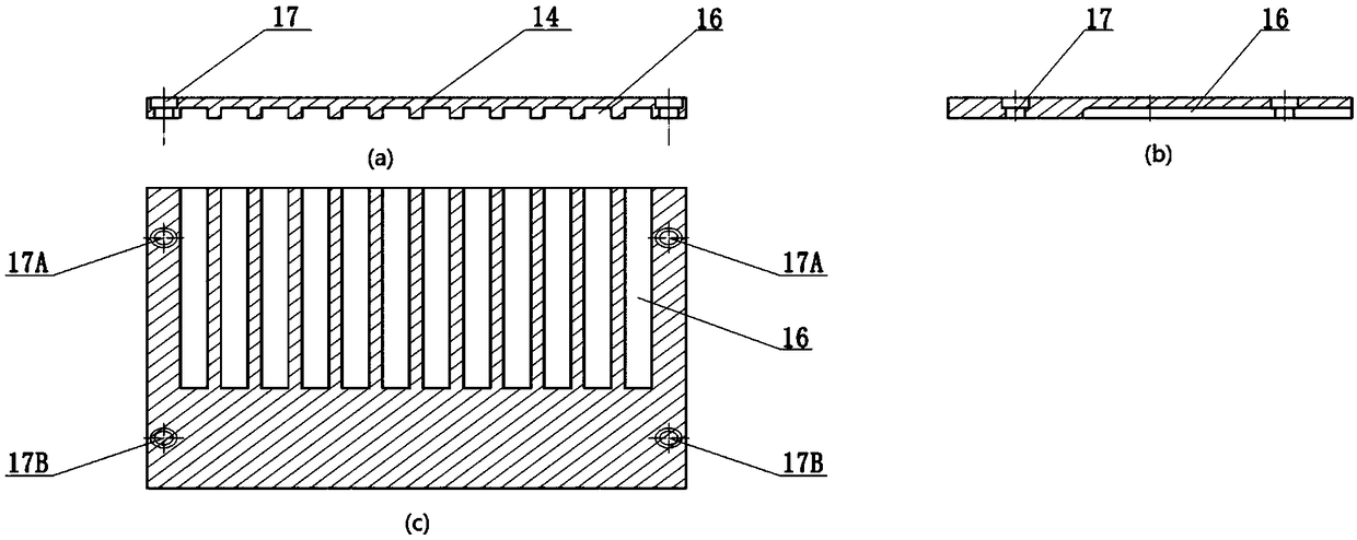
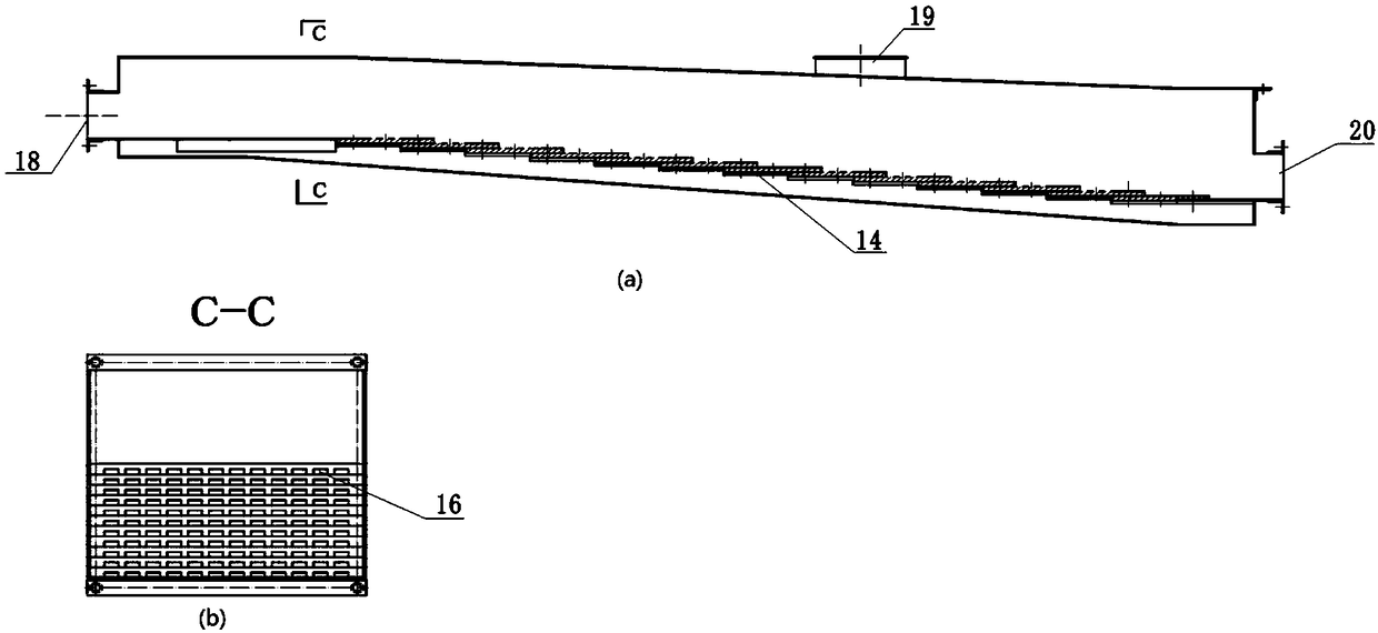
[0031] Such as figure 1 As shown, a medium-high temperature solid powder waste heat recovery device includes a hopper 1, a rotary seal discharge valve 2, a vibration waste heat recovery device 3, a hot air pipeline 4, a cyclone dust collector 5, a storage tank 6, a rotary seal discharge valve Material valve 3 7, rotary sealing discharge valve 2 8, cold air pipeline 9, air blower 10, steel bracket 15; the bottom of hopper 1 is connected with the inlet of rotary sealing discharge valve 1 2 through flange bolts, and the connection is made of high temperature resistant stone Cotton cloth is used for sealing; the bottom of rotary sealing discharge valve 1 2 is softly connected with the entrance of vibration waste heat recovery device 3 through high temperature resistant asbestos; the vibration waste heat recovery device is composed of vibration frame 11, vibration motor 13, vibration spring 12 and air distribution plate 14, the outlet of which is also softly connected with the rota...


PUM


Abstract

The invention belongs to the fields of recovery and utilization of waste heat, and provides a device and a method for recovery of the waste heat from medium-and-high-temperature solid powder. The device comprises a feed hopper, rotary sealing discharge valves, a vibrating waste heat recovery unit, air feeders, a cyclone dust collector, a feed storage tank, a control unit and a detection unit, wherein the lower part of the feed hopper is connected with a solid powder inlet of one end of the vibrating waste heat recovery unit through a rotary sealing discharge valve; the outlet of the other endof the vibrating waste heat recovery unit is connected with the feed storage tank through a rotary sealing discharge valve; the upper end of the vibrating waste heat recovery unit is provided with a hot air outlet which is connected with the cyclone dust collector through a hot air pipeline; and the lower end of the vibrating waste heat recovery unit is provided with air distribution plates and connected with cold air pipelines and the air feeders. The device realizes fluidization of the medium-and-high-temperature solid powder under the action of an airflow, directly contacts with cold air toexchange heat, is highly-efficient and rapid to exchange heat, can adjust the speed of blanking by adjusting the rotating speed of a drive motor for the rotary sealing discharge valves and the vibrating waste heat recovery unit, controls the time of exchanging heat, improves the speed of exchanging heat, and has the advantages of simple structure, low cost and strong applicability.

Description

technical field [0001] The invention belongs to the field of waste heat recovery and utilization, and in particular relates to a medium-high temperature solid powder waste heat recovery device and method. Background technique [0002] In recent years, with the wide application of powder metallurgy technology in the metallurgical industry, such as chromium oxide smelting, soil improver firing, vanadium slag smelting and other industries. A large amount of medium-high temperature powder is produced during the production process, and most of them are mixed with air to recycle the high-temperature air containing powder through convective heat exchange or directly discharge it into the atmosphere. Some enterprises also use traditional water cooling, which not only wastes water resources , Also caused a large amount of heat loss, resulting in greatly reduced energy utilization efficiency, resulting in a large amount of waste of energy. After being mixed with air, the high-tempera...

Claims


Application Information

Patent Timeline
Patent Type & Authority Applications(China)
IPC IPC(8): F28C3/10
CPCF28C3/10
Inventor 董辉罗博张井凡李含竹
Owner NORTHEASTERN UNIV
Learn More