
High temperature and humidity self control energy saving device for setting machine and processing method thereof

A technology of energy-saving device and setting machine, which is applied in control/adjustment system, non-electric variable control, and simultaneous control of multiple variables, etc., can solve the problems of unsatisfactory exhaust gas treatment effect, more waste of production cost, and less exhaust gas recycling and utilization. , to avoid over-drying or insufficient drying, stabilize the humidity in the drying room, and save fuel.

Pending Publication Date: 2018-11-13
绍兴三强机电科技有限公司
View PDF5 Cites 3 Cited by
  • Summary
  • Abstract
  • Description
  • Claims
  • Application Information

AI Technical Summary

Problems solved by technology

[0003] Existing fabric setting machine equipment, during the processing process, the exhaust fan will be rotated at the same power to exhaust at all times, and a large amount of waste gas will be discharged, which consumes a lot of energy; the temperature of the waste gas leaving the heat setting machine is generally 140-170 ℃, and the waste gas It contains a large amount of heat energy that is not fully utilized. If fuel combustion loss and body heat dissipation loss are added, the heat actually consumed for processing fabrics accounts for a small proportion of the total heat input into the setting machine, and there is less recycling of waste gas. More heat loss, resulting in more waste in production costs and higher production costs; in addition, the current treatment effect on waste gas is still not ideal, and the fabric fibers and oil stains in the waste gas can easily lead to fires and form fire hazards. Low safety and high pollution to the environment
Therefore, the existing fabric setting machine equipment has the problems of large energy consumption, high production cost, low safety, and large environmental pollution.

Method used


Image

  • High temperature and humidity self control energy saving device for setting machine and processing method thereof
  • High temperature and humidity self control energy saving device for setting machine and processing method thereof
  • High temperature and humidity self control energy saving device for setting machine and processing method thereof

Examples


Embodiment Construction

[0031] The present invention will be further described below in conjunction with the examples, but not as a basis for limiting the present invention.

[0032] Example.

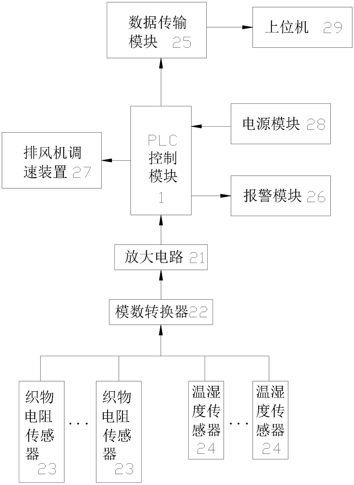
[0033] like figure 1 As shown, a high-temperature and humidity self-control energy-saving device for a sizing machine includes a PLC control module 1, and the PLC control module 1 is connected to a fabric resistance sensor 23 and a temperature and humidity sensor 24 respectively via an amplifier circuit 21 and an analog-to-digital converter 22 in turn, The PLC control module 1 is also connected with a data transmission module 25 , an alarm module 26 , an exhaust fan speed regulating device 27 and a power supply module 28 respectively. Both the fabric resistance sensor 23 and the temperature and humidity sensor 24 are provided with at least two. The temperature and humidity sensor 24 adopts a temperature and humidity sensor 24 whose model is DHT20.

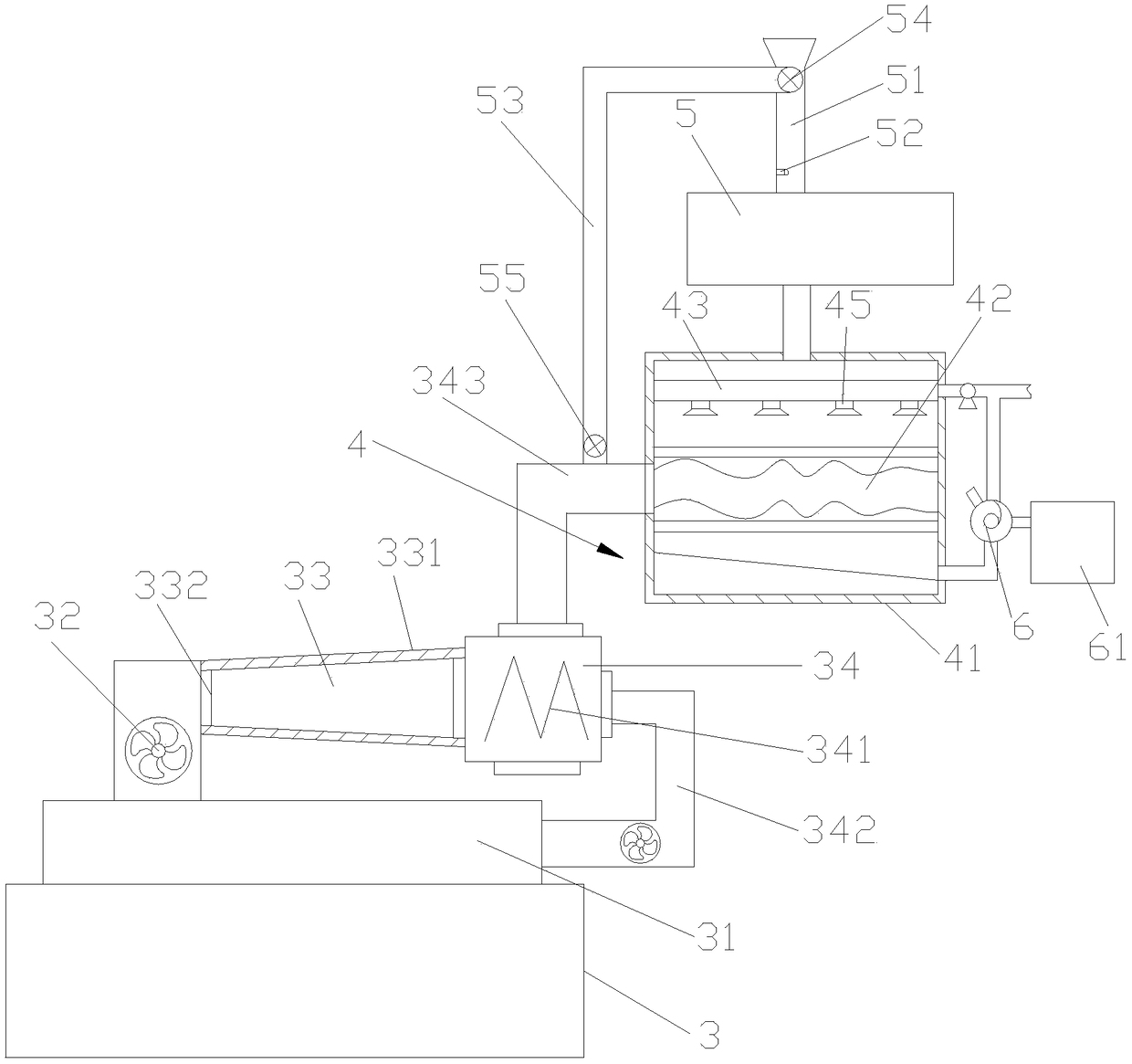
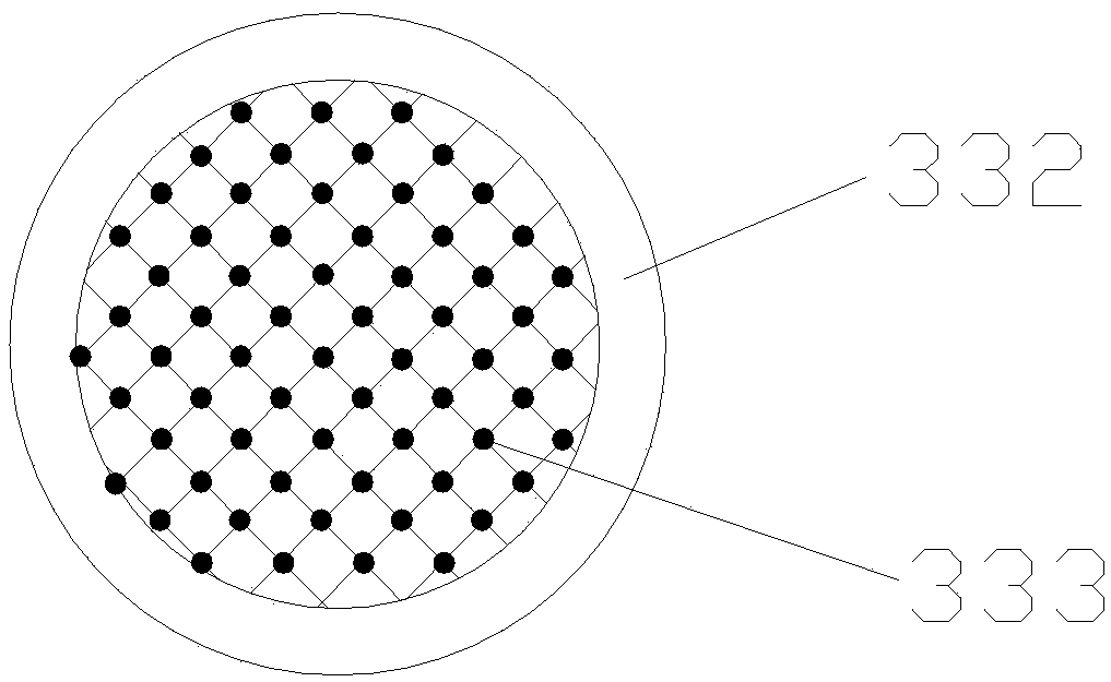
[0034] like figure 2 and image 3As shown, the exhaust ...


PUM


Abstract

The invention discloses a high temperature and humidity self control energy saving device for a setting machine and a processing method thereof. The device disclosed by the invention comprises a PLC control module, wherein the PLC control module is respectively connected with a textile resistance transducer and a temperature and humidity sensor sequentially through an amplification circuit and ananalog-digital converter, and the PLC control module is further respectively connected with an exhaust fan speed regulation device and a power module. The method disclosed by the invention comprises the following steps: A, collecting data; B, uploading data; C, processing data; D, controlling the exhaust fan speed regulation device; E, treating waste gas. The high temperature and humidity self control energy saving device disclosed by the invention has the characteristics of saving energy, reducing production cost, improving safety and reducing environmental pollution.

Description

technical field [0001] The invention relates to an automatic control device of a sizing machine, in particular to a high temperature and humidity automatic control energy-saving device of a sizing machine and a processing method thereof. Background technique [0002] The setting machine is the key equipment in the dyeing and finishing project. The principle of the heat setting machine is a device that uses hot air to dry knitted fabrics or flat fabrics (such as cloth) and resin finishing, and to shape them. Generally, the hot air temperature required in the heat setting machine is about 180°C. Analyzing the overall heat energy consumption of the setting machine, the heat energy loss of the fabric itself after setting is about 3-4% of the heat energy consumption of the overall drying room, and the heat energy loss of the drying room structure is about 3-4%. 5-6% of the heat energy consumption of the drying room, and the exhaust heat release energy accounts for 90-92% of the ...

Claims


Application Information

Patent Timeline
IPC IPC(8): G05D27/02D06C7/02
CPCD06C7/02G05D27/02
Inventor 姚国伟李超唐韬郭云峰陶佳丽高佳菲
Owner 绍兴三强机电科技有限公司
Learn More