
Hazardous waste incineration process

A waste and process technology, applied in incinerators, combustion methods, combustion types, etc., can solve the problems of disordered incineration conditions in the kiln, affecting the quality of flue gas burnout, leachate contamination of groundwater and soil, etc.

Active Publication Date: 2018-11-13
BEIJING BEIKONG ENVIRONMENTAL PROTECTION ENG TECH CO LTD
View PDF5 Cites 4 Cited by
  • Summary
  • Abstract
  • Description
  • Claims
  • Application Information

AI Technical Summary

Problems solved by technology

This way of entering the kiln leads to a large amount of air leakage at the kiln head, causing a series of problems such as uncontrollable oxygen content in the kiln, disordered combustion conditions in the kiln, and frequent supplementary combustion in the secondary combustion chamber.
Moreover, due to the different physical properties of different hazardous wastes, it is easy to cause danger when mixed together. There have been many incidents of inner pit explosions and deflagrations in China.
In addition, the "pit type" feeding method is also prone to leachate pollution of groundwater and soil, and environmental pollution such as air pollution caused by the natural discharge of waste gas
[0005] In addition, the existing hazardous waste treatment system also has many deficiencies in the treatment of slag and tail gas. For example, the slag generally adopts a water-cooled mode, and the water vapor entering the secondary combustion chamber during the cooling process will reduce the combustion temperature of the secondary combustion chamber and affect the flue gas. After burning out the quality, the water-cooled slag is generally dried in the air, and most of the sewage containing high-polluting components in the slag seeps into the ground and enters secondary pollution

Method used


Image

  • Hazardous waste incineration process
  • Hazardous waste incineration process
  • Hazardous waste incineration process

Examples


Embodiment Construction

[0038] The hazardous waste incineration system and process of the present invention will be described in detail below in conjunction with the accompanying drawings. Those skilled in the art should understand that the embodiments described below are only illustrative illustrations of the present invention, and are not intended to limit it in any way.

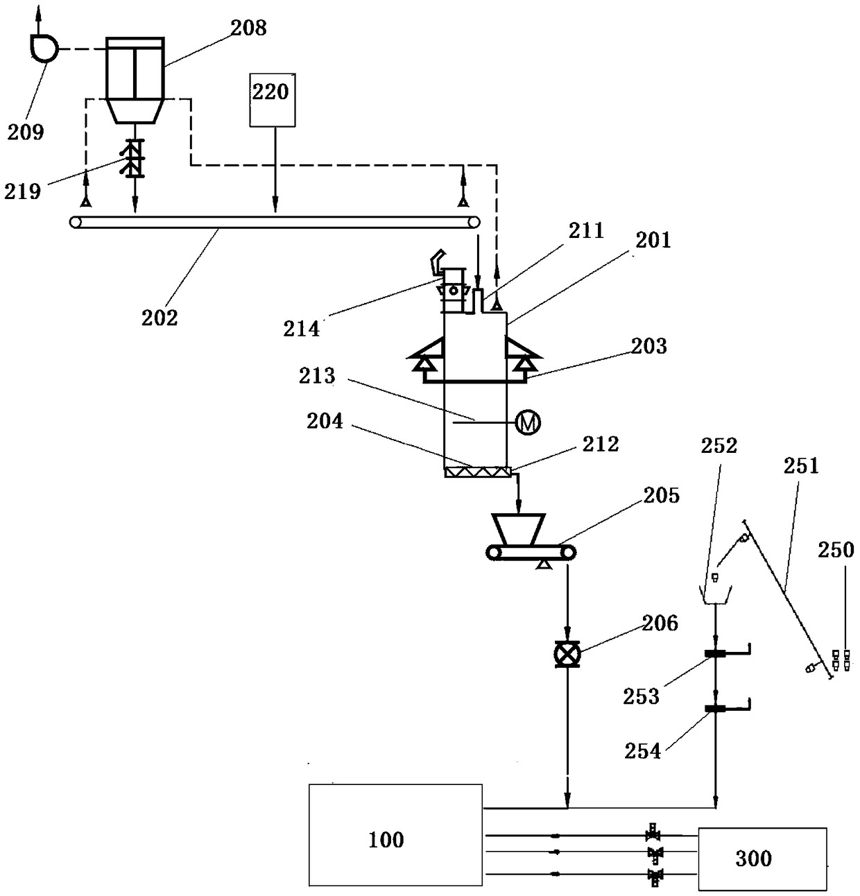
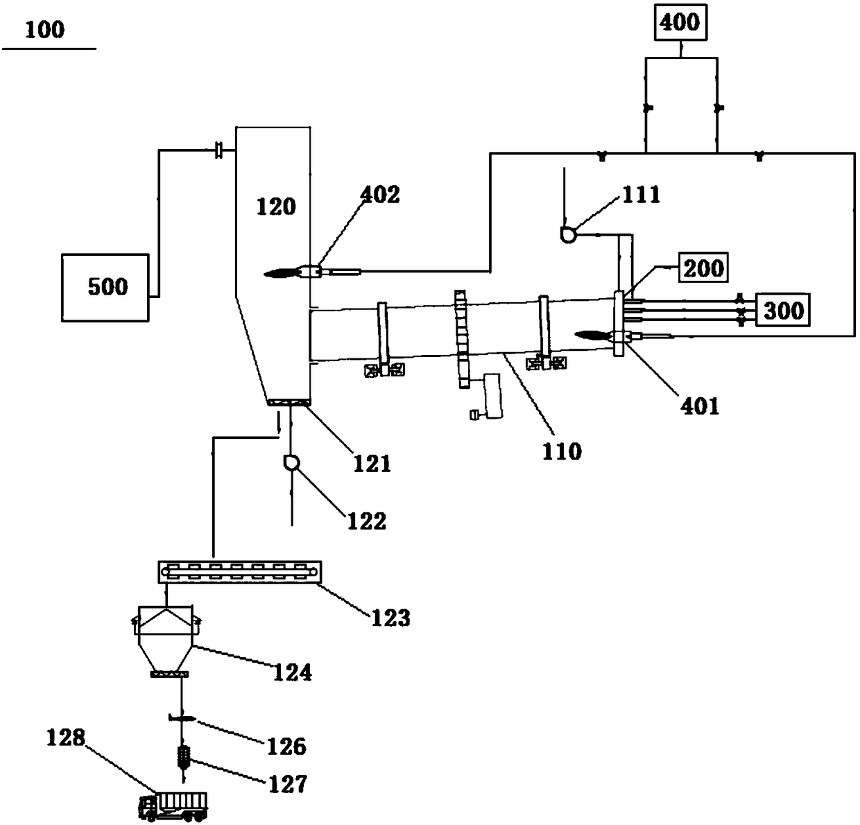
[0039] see Figure 1-Figure 6 , the hazardous waste incineration system according to the present invention mainly includes a feed system, an incineration device 100 and a tail gas treatment system 500 . The structure and working process of each system and device will be introduced in detail below.

[0040] In order to facilitate the compatibility and safe transportation of various materials, in the present invention, the hazardous waste to be treated is divided into three categories in advance: bulk material, bagged material and liquid material. The calorific value and chemical properties of the same type of material are similar...


PUM


Abstract

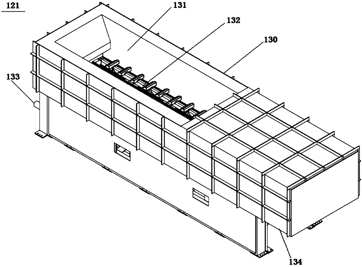
The invention discloses a hazardous waste incineration process. The hazardous waste incineration process comprises the following steps: (1) proportioning a bulk material, a bagged material and a liquid substance according to a preset heat value and chemistry compatibility, and separately feeding the bulk material, the bagged material and the liquid substance in a continuous and airtight mode through a bulk material feeding system, a bagged material feeding system and a liquid substance feeding system; (2) incinerating the fixed carbon part of the hazardous waste in a rotary kiln, wherein volatile combustible gas and fine carbon particles generated in a pyrolysis process into a secondary combustion room to be burned out at a high temperature; and (3) feeding hot slag generated in the rotarykiln and the secondary combustion room into an air cooled slag extractor for heat exchange, and directly conveying the cooled slag to a slag cabin. By adopting the hazardous waste incineration process disclosed by the invention, process parameters in an incineration device are controlled accurately by means of heat value and chemistry compatibility of various hazardous wastes, so that an incineration system is safe, stable and efficient to operate.

Description

[0001] This application is a divisional application of the invention patent application with the application number "201610621423.4", the application date is August 1, 2016, and the invention title is "hazardous waste incineration system and process". technical field [0002] The present invention generally relates to the field of hazardous waste incineration treatment, and more specifically relates to a hazardous waste incineration system and process. Background technique [0003] Hazardous waste (hazardous waste) refers to waste with one or more hazardous characteristics such as corrosiveness, toxicity, flammability, reactivity or infectivity. With the development of industry, the amount of hazardous waste discharged in the industrial production process is increasing, and how to deal with it safely and efficiently is of great significance to environmental safety. [0004] In the existing hazardous waste incineration treatment system, various forms of hazardous waste are us...

Claims


Application Information

Patent Timeline
Patent Type & Authority Applications(China)
IPC IPC(8): F23G5/14F23G5/44F23G5/50F23J1/02F23L15/04
CPCF23G5/02F23G5/14F23G5/442F23G5/444F23G5/446F23G5/50F23G7/04F23G2201/00F23G2203/20F23G2205/00F23G2209/101F23G2900/55F23J1/02F23J15/02F23J15/022F23J2215/10F23J2700/001F23L15/04Y02E20/34
Inventor 李红伟田鑫
Owner BEIJING BEIKONG ENVIRONMENTAL PROTECTION ENG TECH CO LTD
Learn More