
Powder metallurgy self-cleaning mold

A powder metallurgy and self-cleaning technology, applied in the field of molds, can solve the problems of uneven force, the workpiece cannot reach the industrial standard of production, and cannot be further processed, and achieve the effect of stabilizing the feeding speed.

Inactive Publication Date: 2018-11-09
彭勤英
View PDF0 Cites 2 Cited by
  • Summary
  • Abstract
  • Description
  • Claims
  • Application Information

AI Technical Summary

Problems solved by technology

[0003] 1. When the prior art mold is used, it is necessary to align the injection molding device on the injection port of the mold. The flow rate of the injection molding device often flows according to the density of the raw material. When the solution density is small and the speed is fast, It is easy to cause the raw materials to be filled in the mold before they reach the bottom of the mold, and the subsequent raw materials will rush up, and it is easy to bring the external gas into the mold, so that the raw materials are not uniform in the mold, and the processed products Air holes are prone to appear on the surface of the workpiece, making the workpiece not up to the standard of the production industry
[0004] 2. At the same time, when the equipment is carrying out mold removal, it is often used to turn over the top cover and use tools to lift the formed workpiece. The method is not uniform in force, which is very easy to cause damage to the surface of the mold workpiece, causing the workpiece to be partially broken. Inside the mold, the workpiece is scrapped and cannot be further processed

Method used


Image

  • Powder metallurgy self-cleaning mold
  • Powder metallurgy self-cleaning mold
  • Powder metallurgy self-cleaning mold

Examples


Embodiment

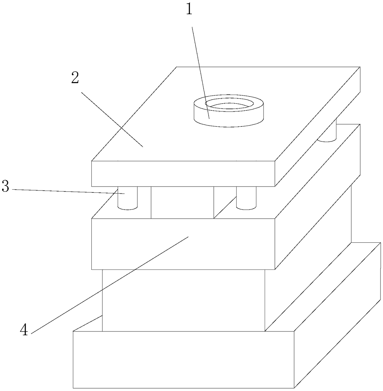
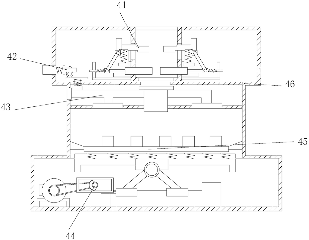
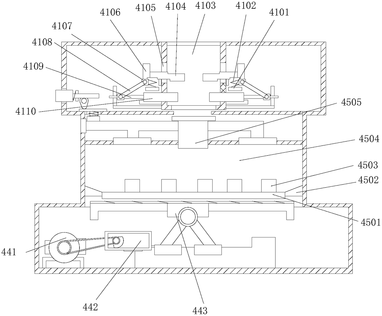
[0024] see Figure 1-Figure 4, the present invention provides a powder metallurgy self-cleaning mould, the structure of which includes an injection port 1, an upper top cover 2, a fixed rod 3, and a body 4. The bottom end of the injection molding port 1 is welded to the top end of the upper top cover 2, and the upper The top cover 2 is located above the body 4, the top end of the fixed rod 3 is vertically embedded in the bottom end of the upper top cover 2, the bottom end of the fixed rod 3 is vertically embedded in the top end of the body 4, and the body 4 includes a flow control Mechanism 41, powder collection drive mechanism 42, powder collection mechanism 43, demoulding mechanism 44, mold forming mechanism 45, shell 46, the top of the flow rate control mechanism 41 is welded to the top of the shell 46, the powder collection drive mechanism 42 Embedded horizontally at the left end of the housing 46, the top of the powder collection mechanism 43 is movably connected with the...


PUM


Abstract

The invention discloses a powder metallurgy self-cleaning mold. The powder metallurgy self-cleaning mold structurally comprises an injection molding hole, an upper top cover, a fixing rod and a machine body, wherein the bottom end of the injection molding hole is welded with the top end of the upper top cover, the upper top cover is located above the machine body, the top end of the fixing rod isvertically embedded into the bottom end of the upper top cover, and the bottom end of the fixing rod is vertically embedded into the top end of the machine body; and the machine body comprises a flowspeed control mechanism, a powder collection driving device, a dust collection mechanism and a demolding mechanism. By improving an internal structure, the size of an injection molding hole can be automatically changed according to the circulation speed of an injection molding device in the injection molding process of the raw materials, and the injection molding circulation speed is steadily controlled, so that the situation that air holes are formed in the surface of a formed workpiece due to the overhigh flow speed is avoided; and meanwhile, the bottom of the mold can be uniformly vibratedduring the mold stripping so as to drive the workpiece to fall, so that the surface abrasion of the workpiece during the prying is avoided.

Description

technical field [0001] The invention relates to the field of molds, in particular to a powder metallurgy self-cleaning mold. Background technique [0002] There are many kinds of molds, which use various methods such as injection molding, blow molding, extrusion, die-casting or forging, smelting, stamping, etc. to press and shape the raw materials in the mold, and make solid workpieces, which are widely used in the market. Large-scale mass production, but the existing molds have the following disadvantages; [0003] 1. When using the mold in the prior art, it is necessary to align the injection molding device on the injection port of the mold. The flow rate of the injection molding device often flows according to the density of the raw material. When the solution density is small and the speed is fast, It is easy to cause the raw materials to be filled in the mold before they reach the bottom of the mold, and the subsequent raw materials will rush up, and it is easy to brin...

Claims


Application Information

Patent Timeline
IPC IPC(8): B22F3/22
CPCB22F3/225
Inventor 彭勤英
Owner 彭勤英
Learn More