
Concrete-filled steel tube arch bridge and construction method

A technology of steel pipe concrete and reinforced concrete, which is applied in the direction of arch bridges, bridges, bridge forms, etc., can solve problems such as difficulty in ensuring the butt joint accuracy of steel pipe arch ribs, difficulty in installing and fixing arch foot formwork, and difficulty in controlling structural stability, and achieves the degree of construction mechanization Improve and ensure the integrity of construction and save the construction period

Pending Publication Date: 2018-10-16
ANHUI HIGHWAY ENG CORP
View PDF0 Cites 31 Cited by
  • Summary
  • Abstract
  • Description
  • Claims
  • Application Information

AI Technical Summary

Problems solved by technology

[0004] During the construction of concrete-filled steel tube arch bridges, it is often difficult to install and fix the arch foot formwork
In the construction process of concrete-filled steel tube arch bridges, it is often difficult to guarantee the butt joint accuracy of steel tube arch ribs, it is difficult to control the structural stability during the construction process, and the labor investment in the installation process of steel tube arch ribs is large, the economy is poor and the construction process is safe. problems such as poor sex
The conventional tie-rod system and suspender construction method of the concrete-filled steel tube arch bridge cannot meet the construction requirements, and the construction steps of the traditional drop frame technology are cumbersome and difficult to organize

Method used


Image

  • Concrete-filled steel tube arch bridge and construction method
  • Concrete-filled steel tube arch bridge and construction method
  • Concrete-filled steel tube arch bridge and construction method

Examples


Embodiment Construction

[0065] The present invention will be further described below in conjunction with the examples. The description of the following examples is provided only to aid the understanding of the present invention. It should be pointed out that for those skilled in the art, without departing from the principle of the present invention, some improvements and modifications can be made to the present invention, and these improvements and modifications also fall within the protection scope of the claims of the present invention.

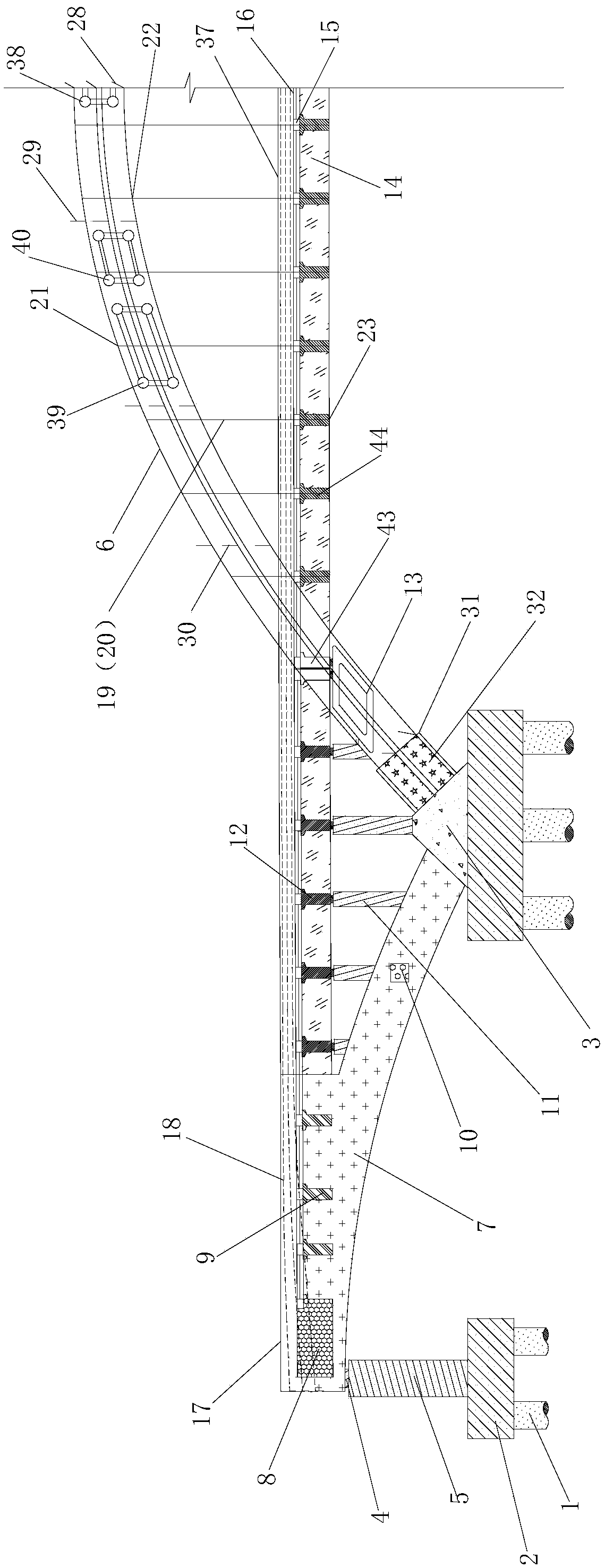
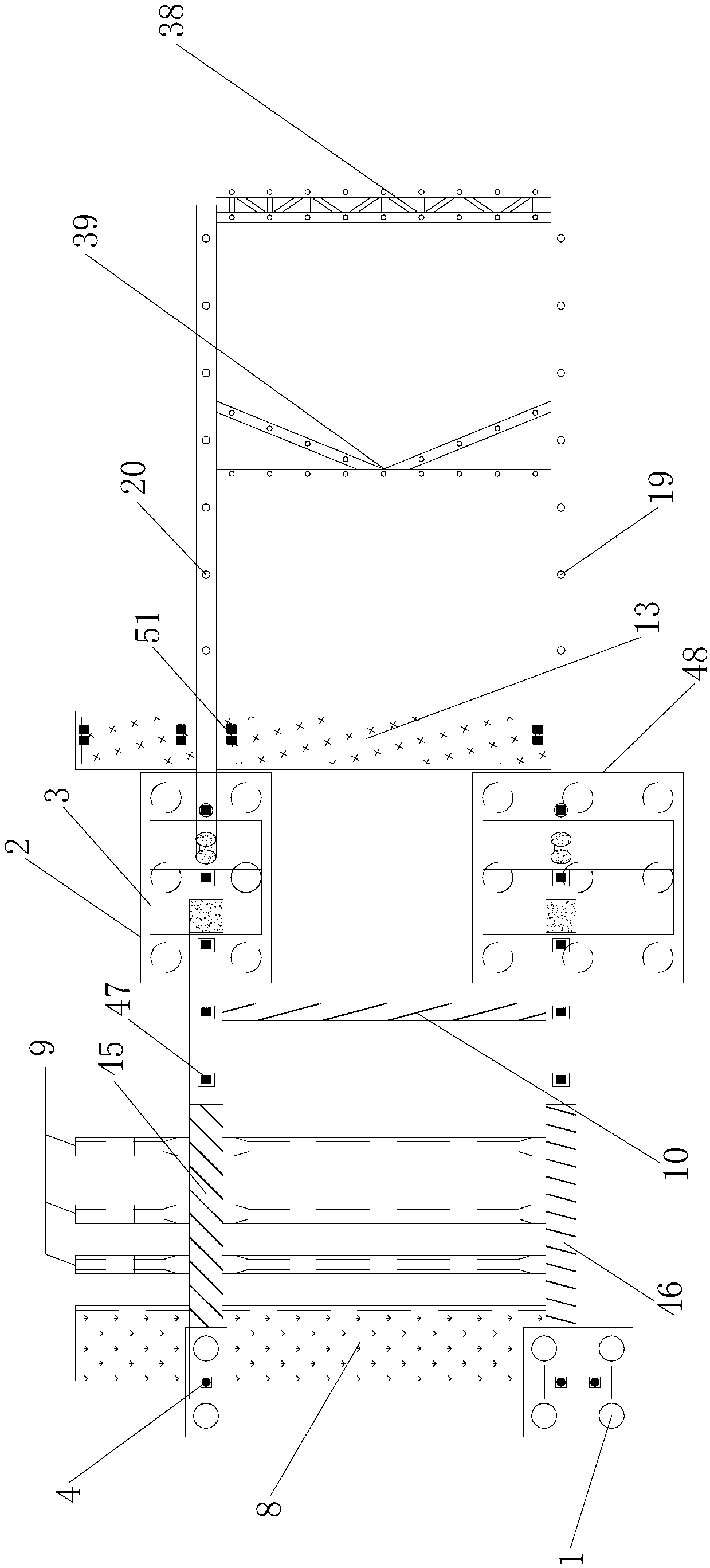
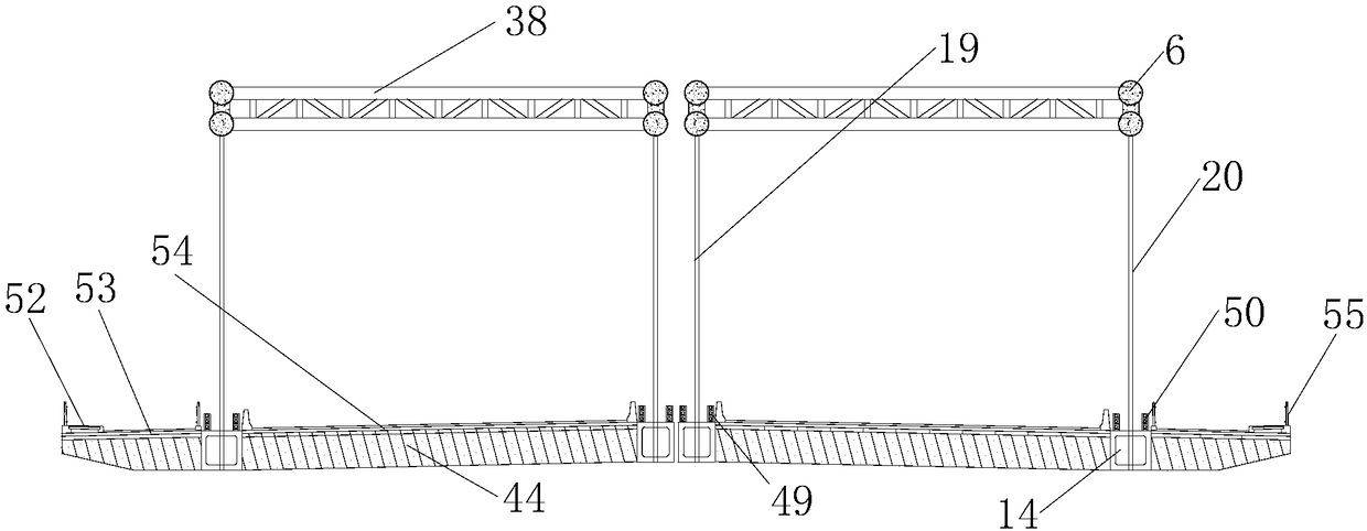
[0066] Such as Figure 1 to Figure 15 As shown, the described steel pipe concrete arch bridge includes: side arch ribs, main arch ribs, suspenders, tie rods and bridge pier structures; side span structures include side arch supports 4, side span cast-in-place reinforced concrete arch ribs 7 , cast-in-place side arch end beam 8, side-span cast-in-place inter-rib beam 9, cast-in-place side arch rib tie beam 10, cast-in-place column 11, flexible prestressed tie bar ...


PUM


Abstract

The invention relates to a concrete-filled steel tube arch bridge. The concrete-filled steel tube arch bridge includes side arch ribs, main arch ribs, suspension bars, tie bars and a bridge pier and abutment structure. Side span structures include side arch supports, side span cast-in-place reinforced concrete arch ribs, cast-in-place side arch end cross beams, side span cast-in-place cross beamsbetween ribs, cast-in-place side arch rib tie beams, cast-in-place side upright posts, flexible prestressed tie bars and cast-in-place bridge deck slabs. Mid-span structures include abutments, mid-span concreted-filled steel tube arch ribs, main arch hollow cross beams between ribs, precast hollow longitudinal beams, flexible prestressed tie beams, tie-bar steel plate boxes, truss-type permanent upper wind braces, K-shaped permanent intermediate wind braces, temporary wind braces, arch foot pre-embedded sections, inner steel strand whole-bundle-squeezed inhaul cable suspension bars and outer steel strand whole-bundle-squeezed inhaul cable suspension bars. The concrete-filled steel tube arch bridge has the beneficial effects that steel tube arch rib fixation brackets involved in the concrete-filled steel tube arch bridge can improve the stability during installation and construction of steel tube arch ribs, and the accuracy of butt joint can be guaranteed effectively.

Description

technical field [0001] The invention relates to a steel pipe concrete arch bridge and a construction method, which belongs to the field of bridge engineering and is suitable for the construction of a Feiyan type steel pipe concrete arch bridge. Background technique [0002] The construction of long-span bridges requires the use of high-strength, lightweight and easy-to-construct engineering materials, and it is hoped that the structure has good ductility and recovery performance. The use of steel tube concrete composite materials in arch bridges can greatly reduce the self-weight of the bridge, and can also improve the structural dynamic performance to a large extent. The arch ribs of CFST arch bridges are mainly compression members, and their stability has always been a concern of bridge engineers. The lateral stiffness of long-span arch bridges is generally small, and large displacements will occur under wind loads, which may affect the normal operation of the bridge stru...

Claims


Application Information

Patent Timeline
IPC IPC(8): E01D4/00E01D21/00
CPCE01D4/00E01D21/00
Inventor 吴德胜夏永红周树标丁贵生宇汝平汪传福王子龙冯晓见吴杨关峰梁辉余国凯杨帆
Owner ANHUI HIGHWAY ENG CORP
Learn More