Vacuum dryer

A dryer and vacuum unit technology, applied in the field of dryers, can solve problems such as energy waste, heat loss, and dead ends of materials, and achieve the effects of reducing operating costs, labor costs, and weight

Inactive Publication Date: 2018-09-25
程相杰
View PDF0 Cites 2 Cited by
  • Summary
  • Abstract
  • Description
  • Claims
  • Application Information

AI Technical Summary

Problems solved by technology

[0002] Circulating hot air dryers, tumble dryers, and hot air drying towers for drying materials on the market now use high-temperature strong air drying, or low-temperature hot air circulation drying, and the drying process is downstream and mixed flow. , countercurrent and combined hot air for grain drying, there are dead ends in the dried materials, the heat energy is for one-time use, and the waste heat cannot be utilized, the materials are easy to form agglomerates, which affects the uneven drying moisture of the materials
Hot air is a one-time use rate, and the moisture is directly discharged into the atmosphere, and its heat energy cannot be recovered, resulting in energy waste
While losing heat and wasting energy, a large amount of dust and impurities are entrained in the air, causing dust pollution and causing harm to human health. Therefore, environmental efficiency cannot be ignored

Method used


Image

  • Vacuum dryer
  • Vacuum dryer
  • Vacuum dryer

Examples


Embodiment Construction

[0111] The present invention will be further described below in conjunction with the accompanying drawings and embodiments.

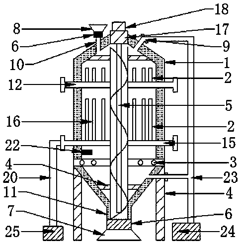
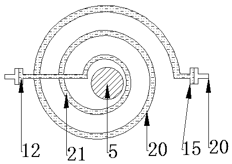
[0112] Such as figure 1 , image 3The shown vacuum dryer includes drying chamber (1), heat exchange device (2), grain discharge device (3), support (4), lifting device (5), valve (6), and feed hopper (8) , discharge hopper (7), sealing device (17), online moisture testing device (22), vacuum unit (24), heating device (25), air pipe (23), heat pipe (20), heat transfer medium (21) , insulation layer (26).

[0113] Such as figure 1 , figure 2 The material of the chamber body (13) of the shown drying chamber (1) is a 3mm metal plate.

[0114] 1. The thermal insulation layer (26) installed on the outside of the warehouse body (13) of the drying warehouse (1) plays the role of heat preservation, and the thermal insulation layer (26) is attached to the warehouse body (13).

[0115] 2. The material for making the insulation layer (26) is a material with ...


PUM


Abstract

The invention discloses a vacuum dryer. The vacuum dryer comprises a drying storehouse, a heat transfer device, grain discharge devices, a bracket, a lifting device, a valve, a feed hopper, an outlethopper, a sealing device, an online moisture test device, a vacuum set, a heating device, a gas guide tube, a heat conduction tube, a heat conduction medium and a thermal insulation layer, wherein thevacuum set is connected with an air exhaust port in the drying storehouse through the heat conduction tube; the valve is used for controlling the entry and exit of materials in the drying storehouse;the heat transfer device is connected with the heating device through the heat conduction tube; the drying storehouse is internally provided with 1-5 sets of grain discharge devices, the online moisture test device is arranged in the drying storehouse; the heat conduction medium carrying thermal energy directly performs heating and heat conducting on the materials through a heat pipe of the heattransfer device, the thermal conversion efficiency is high, loss is small, and the heat conduction and heat transfer speed is improved; waste-heat utilization can be carried out on the heat energy released by the condensable gas in the moisture in the condensation process of a condenser; the lifting device dries the materials circularly and drily; each grain discharge device has a stirring function, so that the drying quality of the materials is even, thereby improving the drying efficiency of the materials and optimizing the drying effect of the materials.

Description

technical field [0001] The invention relates to a dryer, in particular to a vacuum dryer. Background technique [0002] Circulating hot air dryers, tumble dryers, and hot air drying towers for drying materials on the market now use high-temperature strong air drying, or low-temperature hot air circulation drying, and the drying process is downstream and mixed flow. , Countercurrent and combined hot air are used for grain drying. There are dead ends in the dried materials. The heat energy is used for one time, and the waste heat cannot be used. The materials are easy to form agglomerates, which affects the uneven drying moisture of the materials. The hot air is a one-time use rate, and the moisture is directly discharged into the atmosphere, and its heat energy cannot be recovered, resulting in energy waste. While losing heat and wasting energy, a large amount of dust and impurities are entrained in the air, causing dust pollution and causing harm to human health. Therefore,...

Claims


Application Information

Patent Timeline
Patent Type & Authority Applications(China)
IPC IPC(8): F26B11/14F26B23/10F26B25/04F26B25/22F26B5/04
CPCF26B5/04F26B11/14F26B23/10F26B25/04F26B25/22F26B2200/08Y02P70/10
Inventor 程相杰
Owner 程相杰
Why Eureka
Try Eureka