
Stamping and spinning integrated forming device for thin-wall cylinder part with concave bottom and forming method thereof

A technology of thin-walled tube and punching, which is applied in the field of punching and spinning integrated forming device for thin-walled tube with concave bottom, which can solve the problem of difficult to ensure the tightness of thin-walled weld seams, high requirements for workers' welding technology, and complicated spinning forming process and other problems, to achieve the effect of reducing the number of molds and tooling, shortening the forming cycle, and reducing the number of forming passes

Active Publication Date: 2018-09-18
HEFEI UNIV OF TECH
View PDF6 Cites 0 Cited by
  • Summary
  • Abstract
  • Description
  • Claims
  • Application Information

AI Technical Summary

Problems solved by technology

The disadvantages of traditional manufacturing methods are: (1) For thin-walled liquid containers with high internal pressure, the annular weld is a rupture hazard zone; (2) For large-capacity liquid food (beer, etc.) packaging containers, welding heat The affected area is a dangerous area for later corrosion of stainless steel materials; (3) For strong solvents such as alcohol, due to the introduction of heavy metals by flux, long-term storage may easily cause food safety hazards; (4) For cylinders with strict sealing requirements, thin-walled welding It is difficult to guarantee the sealing of the seam, which requires high welding skills for workers
[0004] Spinning forming is a point-by-point plastic forming process with less cutting and no cutting. Its forming accuracy and mechanical properties are high. However, if only a single spinning process is used, the spinning forming process of the cylindrical part with concave bottom is relatively complicated. , the bottom and wall of the tube need to be multi-pass ordinary spinning and thinning spinning, and the production cycle is relatively long

Method used


Image

  • Stamping and spinning integrated forming device for thin-wall cylinder part with concave bottom and forming method thereof
  • Stamping and spinning integrated forming device for thin-wall cylinder part with concave bottom and forming method thereof
  • Stamping and spinning integrated forming device for thin-wall cylinder part with concave bottom and forming method thereof

Examples


Embodiment Construction

[0029] See attached picture.

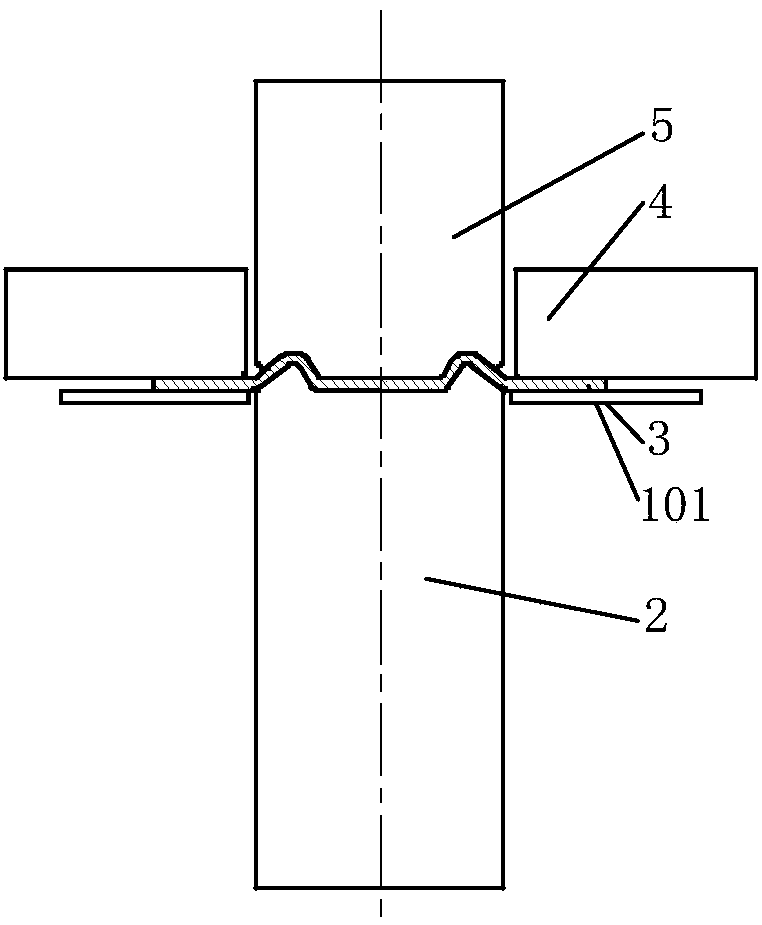
[0030] An integrated punching and spinning forming device for thin-walled cylindrical parts with a concave bottom, including upper and lower templates 12, 13, a movable template 14 is arranged above the upper template 12; a cylindrical punch is installed in the lower template 13 for rotation 2. The punch is controlled to rotate by the hydraulic motor 11. The top surface of the punch 2 is provided with an annular protrusion corresponding to the shape of the bottom of the thin-walled cylinder with a concave bottom. The top of the punch 2 is equipped with a blank holder 3, which 3 and the lower template are provided with a spring 10; the upper template 12 is rotatably equipped with a columnar middle die 5 corresponding to the position of the punch 2, and the bottom surface of the middle die 5 is provided with a ring corresponding to the annular protrusion. Ring-shaped groove, the bottom of the middle die 5 is set with a movable die 4 fixed on the up...


PUM


Abstract

The invention discloses a stamping and spinning integrated forming device for a thin-wall cylinder part with the concave bottom and a forming method thereof. The device structurally comprises an uppermold plate and a lower mold plate, a movable mold plate is arranged above the upper mold plate, a male mold is rotatably arranged in the lower mold plate, an annular protrusion is arranged on the topface of the male mold, the top of the male mold is sleeved with a side pressing ring, a spring is arranged between the side pressing ring and the lower mold plate, a middle female mold is rotatably arranged in the upper mold plate, an annular groove corresponding to the annular protrusion is formed in the bottom face of the middle female mold, the bottom of the middle female mold is sleeved witha movable female mold, the top of the middle female mold is rotatably arranged on the movable mold plate, a rotating wheel frame arranged on a numerical control tool reset is further included, and a rotating wheel is arranged on the rotating wheel frame. The forming process of the thin-wall cylinder part with the concave bottom is simplified, the mold structure is simplified, the forming precisionis improved, and the forming period is shortened.

Description

Technical field: [0001] The invention relates to the technical field of forming a thin-walled cylindrical part with a concave bottom, and mainly relates to a punching-rotation integrated forming device and a forming method for a thin-walled cylindrical part with a concave bottom. Background technique: [0002] Thin-walled cylinders with concave bottoms are widely used in the field of tanks (tubes) for liquid packaging containers. The wall thickness of the cylinder is thin, the ratio of diameter to thickness and height to diameter are large, and the forming accuracy is high, especially for large-capacity liquid containers. In order to stably stand upright and support the weight of the liquid, the bottom needs to be designed as a concave shape with rounded transitions. Based on mechanical calculations and material saving considerations, the waist is designed to be thinner, and the shoulders need to be riveted (or rolled) with the conical cover. Designed to be thicker in order ...

Claims


Application Information

Patent Timeline
Patent Type & Authority Applications(China)
IPC IPC(8): B21D35/00B21D37/10
CPCB21D35/002B21D37/10
Inventor 王成勇陈锦洪叶鹏飞吴进项志伟
Owner HEFEI UNIV OF TECH
Learn More