Wall structure for fixing external wall composite thermal insulation template and construction method

A composite thermal insulation and wall structure technology, applied in the direction of walls, building components, building structures, etc., can solve the problems of falling off, difficult to control the flatness, and bulging and cracking at the joints of the thermal insulation board.

Pending Publication Date: 2018-12-18
陈岩
View PDF0 Cites 0 Cited by
  • Summary
  • Abstract
  • Description
  • Claims
  • Application Information

AI Technical Summary

Problems solved by technology

Such a fixing method cannot effectively fix the formwork before the concrete solidifies, so that the formwork after the concrete solidifies cannot be aligned, is easy to fall off, and is difficult to control the flatness; The decorative layer is damaged, affecting the service life
[0003] When installing the inner formwork, it is necessary to pre-embed the protection tubes for the tension bolts, which will be removed after construction, and the process is complicated;
[0004] In the prior art, it is necessary to use movable positioning rods to ensure the thickness of the wall. The movable positioning rods are used to set the rod-shaped members of specific lengths. When used, they are simply placed between the formwork and the reinforced wall, and they often fall off during construction. Crooked, resulting in uneven thickness of the wall

Method used


Image

  • Wall structure for fixing external wall composite thermal insulation template and construction method
  • Wall structure for fixing external wall composite thermal insulation template and construction method
  • Wall structure for fixing external wall composite thermal insulation template and construction method

Examples


Embodiment Construction

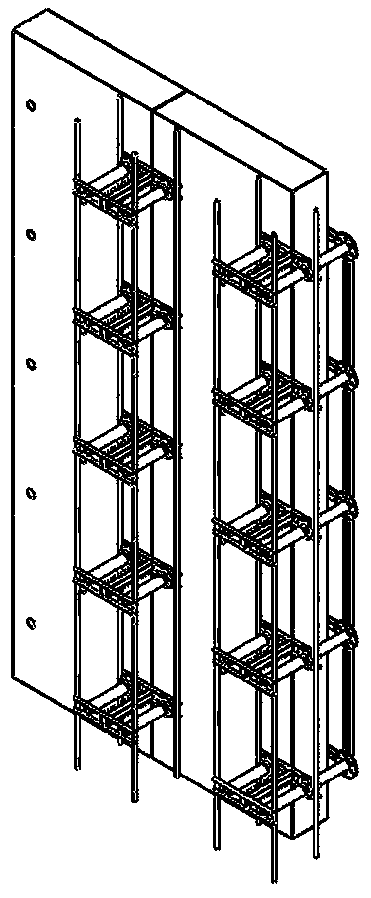
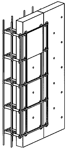
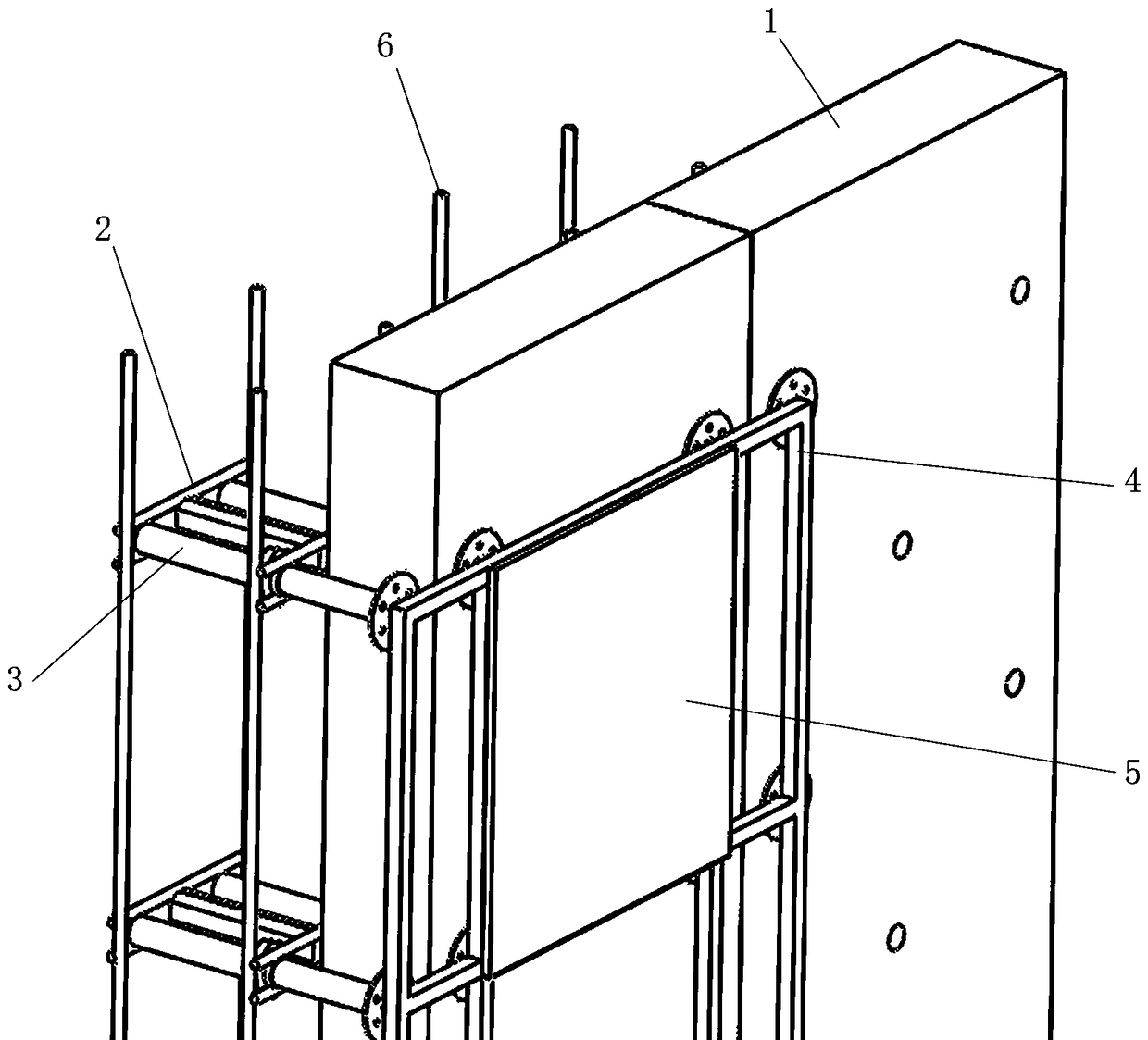
[0042] As shown in the figure, the present invention is the following wall structure:

[0043] The outer side of the structure is a composite thermal insulation formwork 1, and the inner side is a reinforced concrete structure;

[0044] In the reinforced structure of pouring concrete, an I-shaped limiter 2 is erected between the longitudinal steel bars 6; the I-shaped limiter 2 includes a limit column 2-2 and positioning rods 2-1 at both ends of the limit column 2-2, and the positioning The rod 2-1 is located at the head and tail of the limit column 2-2, and two parallel bars are arranged at one end close to the composite thermal insulation formwork 1; the I-shaped limiter is used to accurately limit the thickness of the wall to prevent the formwork from protruding or sagging.

[0045] A nylon rivet 3 is worn in the opening of the composite thermal insulation formwork 1; the nylon rivet 3 passes through the gap between the positioning rods 2-1, and is locked with a nut 7, so t...


PUM


Abstract

A wall structure for fixing external wall composite thermal insulation template is disclosed. A composite thermal insulation template is arranged on an outer side of the structure while a steel bar structure for concrete pouring is arranged on an inner side; in the steel bar structure for concrete pouring, an I-shape limiting device is arranged between longitudinal steel bars in an erected manner,the I-shape limiting device comprises a limiting column and positioning rods positioned on two ends of the limiting column, each of a head end and a tail end of the limiting column is provided with agroup of positioning rods, nylon riveting members are arranged in an open pore of the composite thermal insulation template in a penetrating manner, the nylon riveting members run through gaps between the positioning rods and are locked via screw nuts, and therefore the I-shape limiting device and the composite thermal insulation template are fixed; one end of each nylon riveting member is a positioning disc, a middle segment is provided with an external screw thread, and a center is a via hole. The thermal insulation template is fixed on the I-shaped limiting device via the nylon riveting members and therefore is directly connected with a steel bar wall body, and wall surface thickness and flatness of each template can be accurately controlled before cement is completely solidified. After concrete pouring, the nylon riveting members are firmly connected to a concrete wall, the external thermal insulation template is poured in the concrete wall, and that the external thermal insulation template is permanently fixed to the wall can be ensured.

Description

technical field [0001] The invention belongs to the fields of construction engineering and building exterior wall heat preservation, and in particular relates to a wall structure and a construction method for fixing a composite heat preservation formwork for exterior walls. Background technique [0002] The external wall insulation board in the prior art is easy to fall off and cause fire; the installation method is to suspend plastic expansion nails on the formwork, then erect the formwork on the outside of the reinforced wall, and pour concrete to bury the plastic expansion nails in it, thereby Fixed insulation template. Such a fixing method cannot effectively fix the formwork before the concrete solidifies, so that the formwork after the concrete solidifies cannot be aligned, is easy to fall off, and is difficult to control the flatness; The decorative layer is damaged, affecting the service life. [0003] When installing the inner formwork, it is necessary to pre-embed...

Claims


Application Information

Patent Timeline
IPC IPC(8): E04B2/84E04B2/86
CPCE04B2/84E04B2/86E04B2/8611E04B2002/8682Y02A30/00Y02B30/90
Inventor 陈岩王永怀
Owner 陈岩
Why Eureka
Try Eureka