Multi-beam highly directional three-sided angle reflector antenna based on metasurface
An angle reflective surface and multi-beam technology, which is applied in the fields of antenna, wireless communication and radar, can solve the problems of limited gain improvement, reduced antenna backscattering characteristics, and inability to achieve calibration, so as to effectively increase antenna gain and improve beam Calibration effect, effect of position parameter optimization
- Summary
- Abstract
- Description
- Claims
- Application Information
AI Technical Summary
Problems solved by technology
Method used
Image
Examples
Embodiment 1
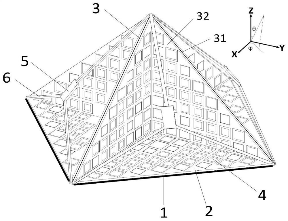
[0037] Refer to figure 1 , A metasurface-based four-beam highly directional three-sided angled reflector antenna, including a metal base plate 1, a dielectric plate 2, four right-angle isolation plates 3, a metal square ring structure 4, four spherical wave feeds 5, and support rods 6.
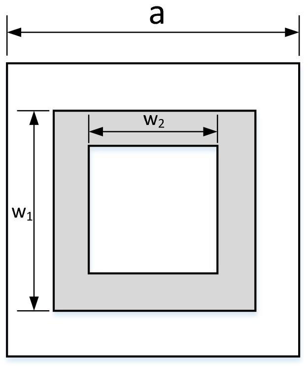
[0038] The metal bottom plate 1 adopts a square with the same size as the medium plate 2. The medium plate 2 and the metal bottom plate 1 form an up-and-down laminated structure, and the metal bottom plate 1 is bonded to the lower surface of the medium plate 2. The metal bottom plate 1 is made of metal Copper material, in order to improve the structural strength of the present invention, the thickness of the metal bottom plate 1 is 0.5mm; the dielectric plate 2 is made of FR4 material, the thickness is 1mm, and the upper surface is printed with M×M metal square ring structures arranged periodically 4. M≥20.
[0039] The M×M metal square ring structures 4 arranged periodically, in theory, when M≥55...
Embodiment 2
[0052] The shape and size of the metal bottom plate 1 and the dielectric plate 2, the number and size of the isolation plates 3, and the number and position of the spherical wave feed source 5 of this embodiment are different from those of the first embodiment, and the other structures and principles are the same as those of the first embodiment. the same.
[0053] This embodiment achieves the performance of five-beam high directional radiation in space. The metal bottom plate 1 and the dielectric plate 2 adopt the same regular pentagonal surface structure with a side length of 102.7mm; five isosceles right-angled triangle isolation plates 3 are fixed respectively On the line connecting the center point of the upper surface of the regular pentagonal medium plate 2 and the five vertices, the length of the two waist sides is 87.4 mm, and the length of the bottom side is 123.6 mm. The phase center positions of the five spherical wave feed sources 5 are respectively 60mm away from th...
Embodiment 3
[0055] The shape and size of the metal base plate 1 and the dielectric plate 2, the number and size of the isolation plates 3, and the number and position of the spherical wave feed source 5 of this embodiment are different from those of the first embodiment, and other structures and principles are the same as those of the first embodiment. the same.
[0056] This embodiment achieves the performance of high directional radiation with six beams in space. The metal base plate 1 and the dielectric plate 2 adopt the same regular hexagonal surface structure with a side length of 98.8mm; six isosceles right-angled triangle isolation plates 3 are respectively fixed on On the diagonal line of the upper surface of the regular hexagonal medium plate 2, the length of the two waist sides is 98.8 mm, and the length of the bottom side is 139.7 mm. The phase center positions of the six spherical wave feed sources 5 are 61mm away from the vertex of the three-sided included angle reflecting surfa...
PUM
 Abstract
Description
Claims
Application Information
 - R&D Engineer
- R&D Manager
- IP Professional
- Industry Leading Data Capabilities
- Powerful AI technology
- Patent DNA Extraction
Browse by: Latest US Patents, China's latest patents, Technical Efficacy Thesaurus, Application Domain, Technology Topic, Popular Technical Reports.
© 2024 PatSnap. All rights reserved.Legal|Privacy policy|Modern Slavery Act Transparency Statement|Sitemap|About US| Contact US: help@patsnap.com


