Temperature self-adaptive current source and optical module
An adaptive and current source technology, applied in the field of optical communication, can solve the problems of increased power consumption of optical modules, decreased communication quality, and shortened lifespan, achieving the effects of reducing power consumption, saving manpower and time, and optimizing high-temperature performance
- Summary
- Abstract
- Description
- Claims
- Application Information
AI Technical Summary
Problems solved by technology
Method used
Image


Examples
Embodiment 1
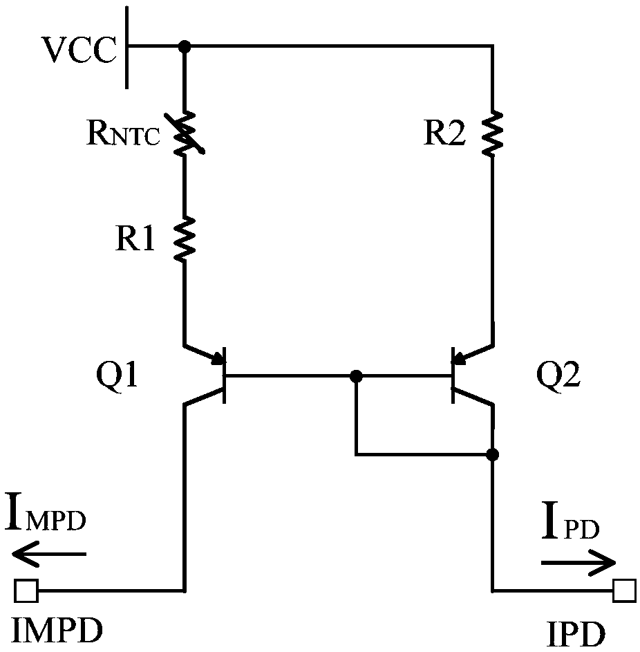
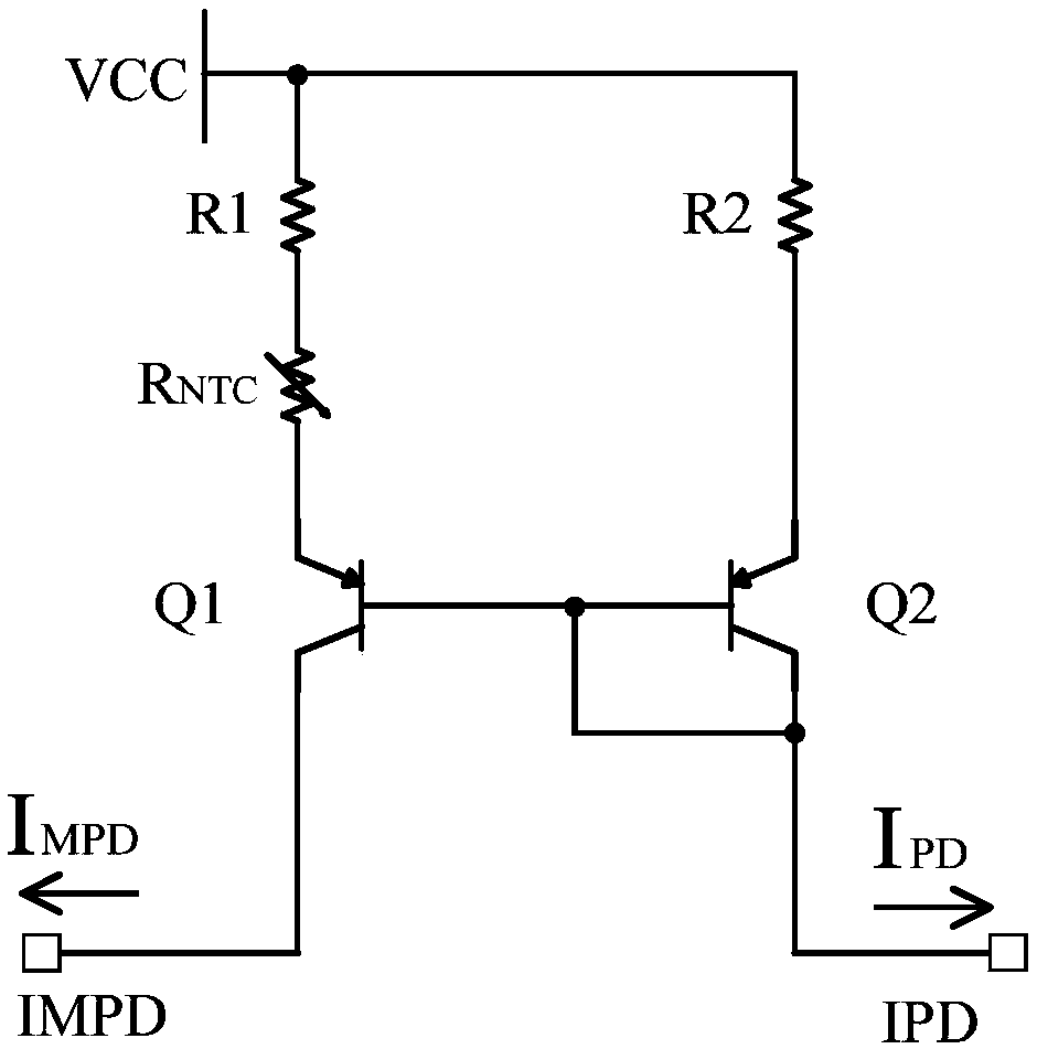
[0045] This embodiment provides a temperature adaptive current source, figure 1 is the circuit diagram of the temperature adaptive current source, the temperature adaptive current source includes a proportional current source, a thermistor R NTC , a power supply terminal, an input terminal IPD and an output terminal IMPD.
[0046] Specifically, the proportional current source includes a reference current branch and an output current branch, and the thermistor R NTC connected in series in the reference current branch or in series in the output current branch; one end of the reference current branch is connected to the input terminal IPD and is adapted to receive the feedback current I from the optical component PD , one end of the output current branch is connected to the output terminal IMPD and is suitable for outputting the sampling current I to the driver chip of the optical component MPD , the sampling current I MPD It is positively correlated with temperature, that is,...
Embodiment 2
[0054] This embodiment provides a temperature adaptive current source, image 3 is the circuit diagram of the temperature adaptive current source. Compared with the temperature adaptive current source provided in Embodiment 1, the difference is that the thermistor R PTC in series with the reference current branch, and the thermistor R PTC A thermistor with a positive temperature coefficient.
[0055] In this embodiment, the thermistor R PTC connected in series between the power supply terminal and one end of the second resistor R2, that is, one end of the second resistor R2 passes through the thermistor R PTC Connect the power supply terminal. Of course, the thermistor R PTC It can also be connected in series between the other end of the second resistor R2 and the emitter of the second PNP transistor Q2, that is, the other end of the second resistor R2 passes through the thermistor R PTC connected to the emitter of the second PNP transistor Q2, as Figure 4 shown.
[0...
Embodiment 3
[0060] This embodiment provides a temperature adaptive current source, Figure 5 is the circuit diagram of the temperature adaptive current source. Compared with the temperature adaptive current source provided in Embodiment 1, the difference is that: the power supply terminal is grounded, the output current branch includes a first resistor R1 and a first NPN transistor Q1, and the reference current branch includes a second Resistor R2 and the second NPN transistor Q2.
[0061] Specifically, one end of the first resistor R1 is used as the other end of the output current branch, that is, one end of the first resistor R1 is connected to the power supply end, and the other end of the first resistor R1 is connected to the first An emitter of an NPN transistor Q1, the base of the first NPN transistor Q1 is connected to the base of the second NPN transistor Q2 and the collector of the second NPN transistor Q2, and the collector of the first NPN transistor Q1 The electrode is used ...
PUM
 Abstract
Description
Claims
Application Information
 - R&D
- Intellectual Property
- Life Sciences
- Materials
- Tech Scout
- Unparalleled Data Quality
- Higher Quality Content
- 60% Fewer Hallucinations
Browse by: Latest US Patents, China's latest patents, Technical Efficacy Thesaurus, Application Domain, Technology Topic, Popular Technical Reports.
© 2025 PatSnap. All rights reserved.Legal|Privacy policy|Modern Slavery Act Transparency Statement|Sitemap|About US| Contact US: help@patsnap.com