
Optical reflectivity surface treatment method

A surface treatment, optical reflection technology, applied in the direction of anodizing, can solve the problems of poor wear resistance, poor light resistance, easy conductivity, etc., to improve wear and corrosion resistance, strong selective absorption and scattering effects Effect

Active Publication Date: 2018-08-24
国泰达鸣精密科技集团有限公司
View PDF11 Cites 1 Cited by
  • Summary
  • Abstract
  • Description
  • Claims
  • Application Information

AI Technical Summary

Problems solved by technology

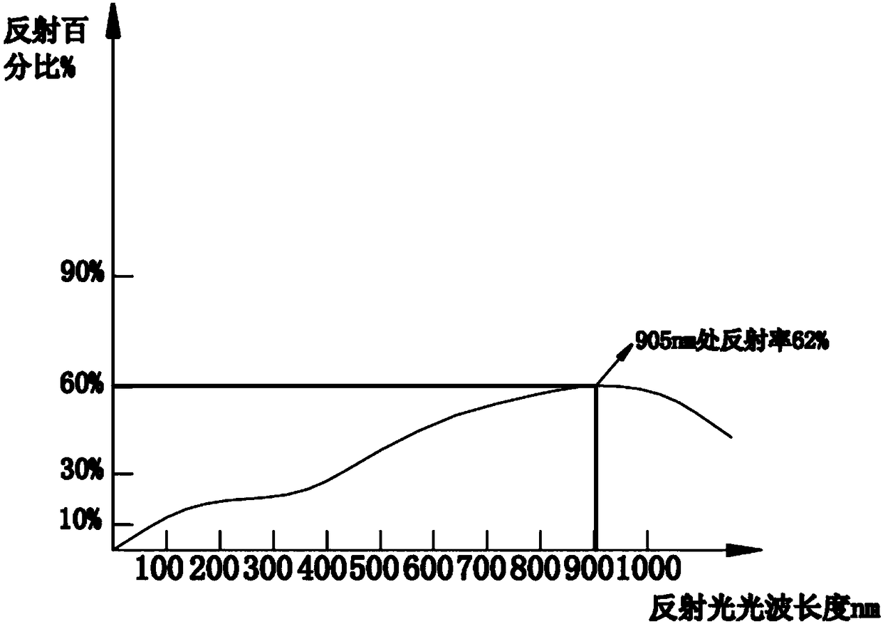
[0003] The existing surface treatment mainly includes normal temperature blackening treatment and ordinary anodic oxidation on the surface of ordinary products, and the disadvantages of the normal temperature blackening treatment process on the surface of ordinary products are 1. The film formed by conductive oxidation is only 0.01-0.15 microns, and the wear resistance is not good ; 2. The oxide film is thin, easy to conduct electricity, and cannot be used as an insulation protection product; 3. After blackening, the blackened layer only absorbs a small amount of light, and most of it is reflected, and the reflectivity is high (the reflectivity is above 80%) )
[0004] The disadvantages of ordinary anodizing are 1. Compared with optical black anodizing, the oxide film is wear-resistant, light-resistant, and light-resistant; 2. After ordinary anodizing, the blackened layer also absorbs part of the light. Reflection (reflectivity above 60%)
[0005] At present, there is no blackening process that can reduce the optical reflectance of the product surface to a very small value. The general blackened surface treatment can only reduce the optical reflectance to about 60% at most.

Method used


Image

  • Optical reflectivity surface treatment method
  • Optical reflectivity surface treatment method
  • Optical reflectivity surface treatment method

Examples


Embodiment Construction

[0023] In order to have a clearer understanding of the technical features, purposes and effects of the present invention, the specific implementation manners of the present invention will now be described with reference to the accompanying drawings.

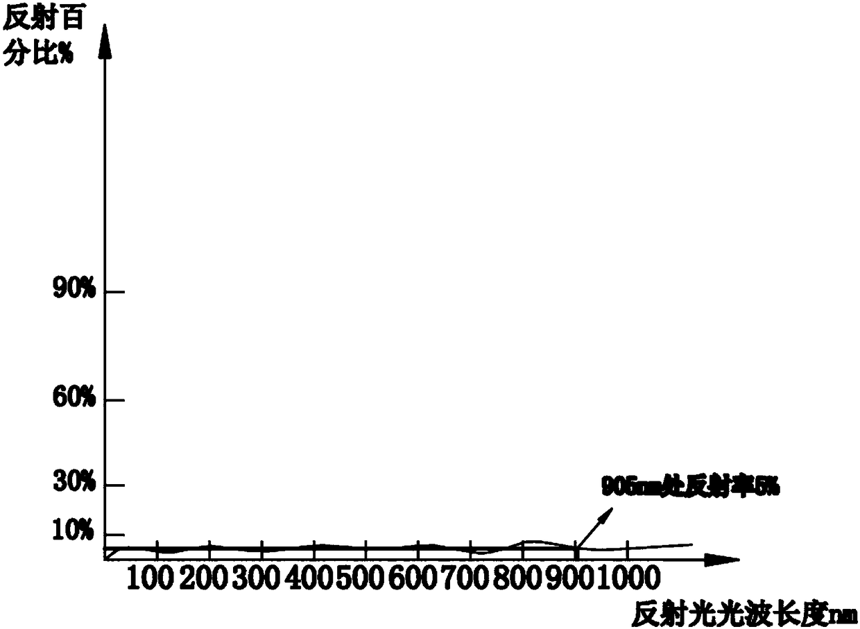
[0024] The optical reflectivity surface treatment method of the present invention has greatly improved the surface performance of the product, especially in the optical reflectivity, can greatly reduce the reflectivity, so that the product surface can meet the assembly requirements of optical devices, and will be due to Light reflected from the housing has minimal impact on the optics.

[0025] A kind of optical reflectivity surface treatment method of the present invention, in its preferred embodiment, please refer to figure 1 Shown, be the flow chart diagram of preferred embodiment of the present invention, this method comprises the following steps to the processing of product:

[0026] S101 After placing the product on the pr...


PUM


Abstract

The invention discloses an optical reflectivity surface treatment method. The optical reflectivity surface treatment method comprises the following steps that a product is placed on a product fixing frame, product surface oil contamination is removed through degreasing an water washing working procedures, and the product is cleaned; primary anodic oxidation treatment is carried out, and a sulfuricacid solution is adopted for carrying out primary anodic oxidation on the product; water washing is carried out after primary anodic oxidation, an alkaline solution is used for neutralization, and cleaning is carried out through water washing; sealed pretreatment is carried out, an activating agent is adopted for carrying out sealed pretreatment on the product; neutralization and water washing treatment is carried out after sealed pretreatment; secondary anodic oxidation treatment is carried out, and a sulfuric acid solution is adopted for carrying out secondary anodic oxidation on the product; water washing and neutralization are carried out after secondary anodic oxidation treatment, and water washing treatment is carried out; sealing treatment is carried out, and nickel fluoride and activating agent are adopted for carrying out sealing treatment on the product; and after sealing treatment, cleaning, drying and appearance detection are carried out, and the product is packaged. The product surface optical reflectivity is effectively reduced.

Description

technical field [0001] The invention relates to a surface treatment process, in particular to an optical reflectivity surface treatment method capable of effectively reducing the optical reflectivity of a metal surface. Background technique [0002] On the surface of many products, especially the products with high requirements on the surface quality of the shell, the surface of the product is generally processed, and most of them are blackened. At present, there are two main methods of blackening the product; one is the surface of ordinary products. Blackening treatment is generally a chemical reaction under the condition of high temperature solution (alkali + ammonium nitrite + water). Its purpose is mainly to prevent rust, not for appearance parts and precision products. Electrolytic reaction occurs in sulfuric acid solution, this method is mainly for products with high requirements on appearance and dimensional accuracy. However, for some optical components, not only th...

Claims


Application Information

Patent Timeline
IPC IPC(8): C25D11/02
CPCC25D11/02
Inventor 王南南温武警谭锦升
Owner 国泰达鸣精密科技集团有限公司
Learn More