Centrifugal pump impeller surface treatment method and equipment
A centrifugal pump impeller, surface treatment technology, applied in the direction of ion implantation plating, coating, metal material coating process, etc. Effect
- Summary
- Abstract
- Description
- Claims
- Application Information
AI Technical Summary
Problems solved by technology
Method used
Image

Examples
Embodiment 1
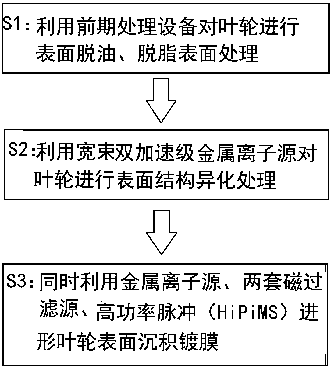
[0057] S1: When wet spraying the surface of the substrate, the particle size of the sand is 200-500 mesh, and the wet spraying treatment time is 60-120s; then immerse the substrate in acetone and alcohol for ultrasonic cleaning to remove oil and fat.
[0058] S2: Ti target is used as the cathode, the ion energy of the metal ion source is 80KeV, and the beam intensity is 6mA;
[0059] S3: Magnetic filtration deposition, the first magnetic filtration target is Cr with an arcing current of 100A; the second magnetic filtration target is TiAl, and the arcing current is 100A. The high-power pulsed magnetron sputtering target is alumina, the deposition arc current is 80A, the frequency is adjusted to 600HZ, the pulse width is 100 microseconds, and the peak power is 1MW; the defocus line package frequency is 500HZ, the current is 60A, and the motor rotation speed is 100 revolutions per minute, the mixed gas of acetylene and nitrogen is mixed according to 1:1, the gas volume is S=250si...
Embodiment 2
[0061] S1: When wet spraying the surface of the substrate, the particle size of the sand is 200-500 mesh, and the wet spraying treatment time is 60-120s; then immerse the substrate in acetone and alcohol for ultrasonic cleaning to remove oil and fat.
[0062] S2: Ti target is used as the cathode, the ion energy of the metal ion source is 80KeV, and the beam intensity is 6mA;
[0063] S3: Magnetic filtration deposition, the first magnetic filtration target is Cr with an arcing current of 100A; the second magnetic filtration target is TiAl, and the arcing current is 100A. The high-power pulsed magnetron sputtering target is alumina, the deposition arc current is 80A, the frequency is adjusted to 600HZ, the pulse width is 100 microseconds, and the peak power is 1MW; the defocus line package frequency is 500HZ, the current is 60A, and the motor rotation speed is 200 revolutions per minute, the mixed gas of acetylene and nitrogen is mixed according to 1:1, the gas volume is S=250si...
Embodiment 3
[0065] S1: When wet spraying the surface of the substrate, the particle size of the sand is 200-500 mesh, and the wet spraying treatment time is 60-120s; then immerse the substrate in acetone and alcohol for ultrasonic cleaning to remove oil and fat.
[0066] S2: Ti target is used as the cathode, the ion energy of the metal ion source is 80KeV, and the beam intensity is 6mA;
[0067] S3: Magnetic filtration deposition, the first magnetic filtration target is Cr with an arcing current of 100A; the second magnetic filtration target is TiAl, and the arcing current is 100A. The high-power pulsed magnetron sputtering target is alumina, the deposition arc current is 80A, the frequency is adjusted to 600HZ, the pulse width is 100 microseconds, and the peak power is 1MW; the defocus line package frequency is 500HZ, the current is 60A, and the motor rotation speed is 250 revolutions per minute, the mixed gas of acetylene and nitrogen is mixed according to 1:1, the gas volume is S=250si...
PUM
 Abstract
Description
Claims
Application Information
 - Generate Ideas
- Intellectual Property
- Life Sciences
- Materials
- Tech Scout
- Unparalleled Data Quality
- Higher Quality Content
- 60% Fewer Hallucinations
Browse by: Latest US Patents, China's latest patents, Technical Efficacy Thesaurus, Application Domain, Technology Topic, Popular Technical Reports.
© 2025 PatSnap. All rights reserved.Legal|Privacy policy|Modern Slavery Act Transparency Statement|Sitemap|About US| Contact US: help@patsnap.com