Welding station pressure monitoring system and monitoring method
A pressure monitoring, welding station technology, applied in force/torque/work measuring instruments, measuring devices, instruments, etc., can solve the problem of real-time monitoring without pre-tightening force, affecting whether the production can be carried out normally, difficult to deal with emergencies, etc. problems, to achieve the effect of saving resources, fast and accurate maintenance, and convenient and unified control
- Summary
- Abstract
- Description
- Claims
- Application Information
AI Technical Summary
Problems solved by technology
Method used
Image
Examples
specific Embodiment 1
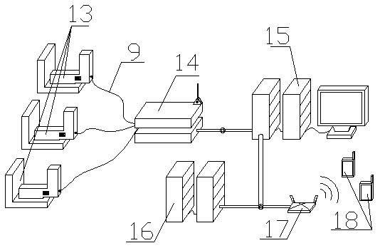
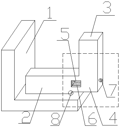
[0050] Such as figure 1 , Figure 5 and Figure 6 As shown, the chuck of the clamp 13 includes a fixed part 2, a force receiving part 3 and a deformation part 4, the fixed part 2 is fixedly connected with the platform 1, and the force receiving part 3 is used to bear external pressure, the external The pressure can cause deformation of the deformation part 4, and a pressure sensing device is attached and fixed to the deformation part of the deformation part 4, and the pressure sensing device is connected to the data post-processing device in signal connection, and the deformation part 4 is respectively connected with the force The part 3 and the fixed part 2 are fixedly connected, and a fulcrum mechanism 8 is installed between the fixed part 2 and the deformable part 4 .
[0051] The fixed part 2 is a bar-shaped or plate-shaped structure or other irregular-shaped structures, wherein the fixed part 2 is fixedly connected to the platform 1 by means of connection including but ...
specific Embodiment 2
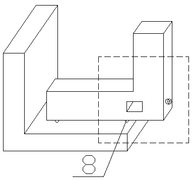
[0055] figure 1 ,Such as Figure 7 and Figure 8 As shown, the chuck of the clamp 13 includes a fixed part 2, a force receiving part 3 and a deformation part 4, the fixed part 2 is fixedly connected with the platform 1, and the force receiving part 3 is used to bear external pressure, the external The pressure can cause deformation of the deformation part 4, and a pressure sensing device is attached and fixed to the deformation part of the deformation part 4, and the pressure sensing device is connected to the data post-processing device in signal connection, and the deformation part 4 is respectively connected with the force The part 3 and the fixed part 2 are fixedly connected, and a fulcrum mechanism 8 is installed between the fixed part 2 and the deformable part 4 .
[0056] The fixed part 2 is a bar-shaped or plate-shaped structure or other irregular-shaped structures, wherein the fixed part 2 is fixedly connected to the platform 1 by means of connection including but n...
specific Embodiment 3
[0060] Such as figure 1 , Figure 9 and Figure 10 As shown, the chuck of the clamp 13 includes a fixed part 2, a force receiving part 3 and a deformation part 4, the fixed part 2 is fixedly connected with the platform 1, and the force receiving part 3 is used to bear external pressure, the external The pressure can cause deformation of the deformation part 4, and a pressure sensing device is attached and fixed to the deformation part of the deformation part 4, and the pressure sensing device is connected to the data post-processing device in signal connection, and the deformation part 4 is respectively connected with the force The part 3 and the fixed part 2 are fixedly connected, and a fulcrum mechanism 8 is installed between the fixed part 2 and the deformable part 4 .
[0061] The fixed part 2 is a bar-shaped or plate-shaped structure or other irregular-shaped structures, wherein the fixed part 2 is fixedly connected to the platform 1 by means of connection including but...
PUM
 Abstract
Description
Claims
Application Information
 - R&D Engineer
- R&D Manager
- IP Professional
- Industry Leading Data Capabilities
- Powerful AI technology
- Patent DNA Extraction
Browse by: Latest US Patents, China's latest patents, Technical Efficacy Thesaurus, Application Domain, Technology Topic, Popular Technical Reports.
© 2024 PatSnap. All rights reserved.Legal|Privacy policy|Modern Slavery Act Transparency Statement|Sitemap|About US| Contact US: help@patsnap.com


