
Full-automatic numerical control bar cutting machine for silicon crystal bar

A silicon crystal rod, fully automatic technology, applied in the field of automatic silicon crystal plate numerical control rod cutting machine, can solve the problems of low work efficiency, air pollution, time-consuming and other problems, and achieve high work efficiency, high degree of automation, and no dust pollution. Effect

Pending Publication Date: 2018-08-07
江阴华芯源半导体装备有限公司
View PDF0 Cites 1 Cited by
  • Summary
  • Abstract
  • Description
  • Claims
  • Application Information

AI Technical Summary

Problems solved by technology

[0002] The silicon crystal rod needs to be cut and polished to the required size before use. Since the silicon crystal rod itself is relatively brittle, in order to avoid its fragmentation during the cutting process, the existing technology generally uses a cylindrical grinder to grind it to meet the requirements of the silicon crystal rod. size, but this kind of grinding takes 8-10 hours to process a silicon ingot, which is very time-consuming, low work efficiency, and a lot of dust will be generated during the grinding process, which cannot be collected for reuse. At the same time, it will pollute the air and affect the health of operators.

Method used


Image

  • Full-automatic numerical control bar cutting machine for silicon crystal bar
  • Full-automatic numerical control bar cutting machine for silicon crystal bar
  • Full-automatic numerical control bar cutting machine for silicon crystal bar

Examples


Embodiment Construction

[0013] All features disclosed in this specification, or steps in all methods or processes disclosed, may be combined in any manner, except for mutually exclusive features and / or steps.

[0014] Any feature disclosed in this specification (including any appended claims, abstract and drawings), unless expressly stated otherwise, may be replaced by alternative features which are equivalent or serve a similar purpose. That is, unless expressly stated otherwise, each feature is one example only of a series of equivalent or similar features.

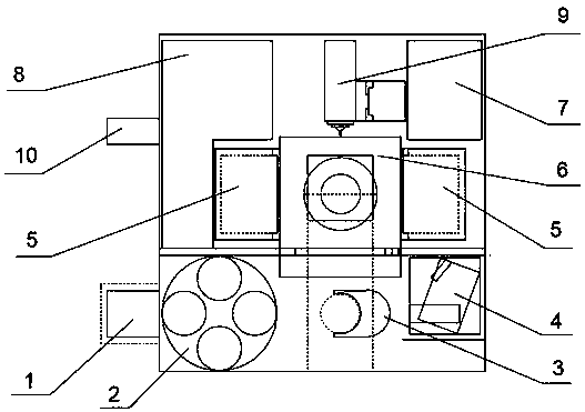
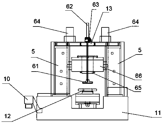
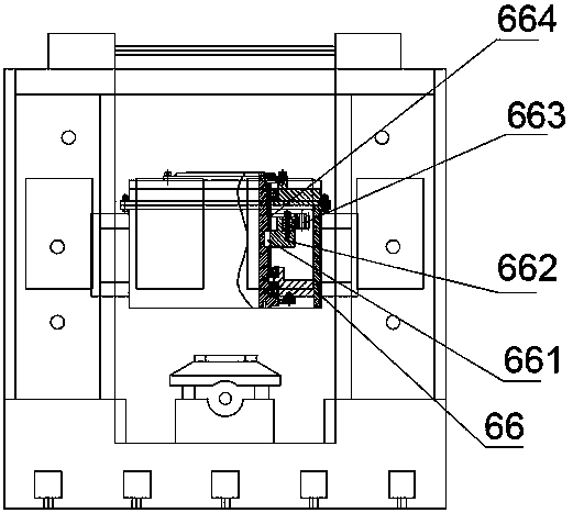
[0015] Such as figure 1 , 2 , a fully automatic silicon crystal ingot numerically controlled rod drawing machine shown in 3, comprising a feeding area 1, a feed bin 2 and a knife rest 6, the feed bin 2 and the knife rest 6 are arranged on a base 11, and the feed bin 2 is Circular rotating disk, multiple grooves are evenly arranged on the bin 2, the feeding area 1 is connected to the bin 2, the silicon crystal rods in the feeding area 1 fall ...


PUM


Abstract

The invention discloses a full-automatic numerical control bar cutting machine for a silicon crystal bar. The machine comprises a feeding area, a stock bin and a tool rest; the stock bin is connectedto the feeding area; a mechanical arm is arranged between the stock bin and the tool rest; a cutter head is arranged on the tool rest; a grooving power head is arranged behind the tool rest; an automatic chip discharging head is arranged on the side surface of the tool rest, and the tool rest is erected on stand columns and comprises a lifting sleeve capable of ascending and descending vertically;a rotatable rotating sleeve is arranged in the lifting sleeve; the tool disc is connected to the bottom of the rotating sleeve; and a pressure plate is arranged in the center of the tool rest. According to the machine, after the silicon crystal bar enters the stock bin from the feeding area, the silicon crystal bar is clamped to the position below the tool rest through the mechanical arm, the pressure plate presses the silicon crystal bar downwards so as to press and position the silicon crystal bar, descending of the tool rest and rotating of the rotating sleeve enable the tool disc to carryout outer cylindrical cutting on the silicon crystal bar, and cut excess materials fall into the automatic chip discharging head to be collected and recycled. The machine has the advantages that theautomation degree is high, dust pollution can be avoided, the excess materials can be collected and recycled, so that energy conservation and environmental protection can be realized, only one hour isneeded for cutting each time, and the working efficiency is high.

Description

technical field [0001] The invention relates to a full-automatic silicon crystal plate numerical control rod-cutting machine. Background technique [0002] The silicon crystal rod needs to be cut and polished to the required size before use. Since the silicon crystal rod itself is relatively brittle, in order to avoid its fragmentation during the cutting process, the existing technology generally uses a cylindrical grinder to grind it to meet the requirements of the silicon crystal rod. size, but this kind of grinding takes 8-10 hours to process a silicon ingot, which is very time-consuming, low work efficiency, and a lot of dust will be generated during the grinding process, which cannot be collected for reuse. At the same time, it will pollute the air and affect the health of operators. Contents of the invention [0003] The invention relates to a full-automatic silicon crystal ingot numerical control ingot drawing machine, which is used to solve the above-mentioned pro...

Claims


Application Information

Patent Timeline
IPC IPC(8): B28D5/02B28D7/00B28D7/02B28D7/04
CPCB28D5/0058B28D5/0076B28D5/0082B28D5/022
Inventor 王江华蔡毅祥冯君
Owner 江阴华芯源半导体装备有限公司
Learn More