
A post-converter decarburization process

A process method and decarburization technology, which is applied in the field of iron and steel smelting, can solve the problems of molten steel overoxidation, high cost, and reduced converter lining life, and achieve the effects of reducing oxide inclusions, simplifying the smelting process, and reducing production costs

Active Publication Date: 2020-02-07
HUNAN VALIN XIANGTAN IRON & STEEL CO LTD
View PDF7 Cites 0 Cited by
  • Summary
  • Abstract
  • Description
  • Claims
  • Application Information

AI Technical Summary

Problems solved by technology

Now, the normal smelting process for this kind of ultra-low-carbon steel is to blow oxygen and decarburize the molten steel in the later stage of converter smelting, which greatly reduces the life of the converter lining, and also causes serious peroxidation of the molten steel. It is more difficult to remove deoxidation and oxide inclusions, which is not conducive to the smelting of clean steel and greatly increases the cost
There are also a small number of iron and steel enterprises that use vacuum decarburization when producing this type of steel. The effect of vacuum decarburization is very good, but the cost is too high

Method used


Image

  • A post-converter decarburization process

Examples


Embodiment 1

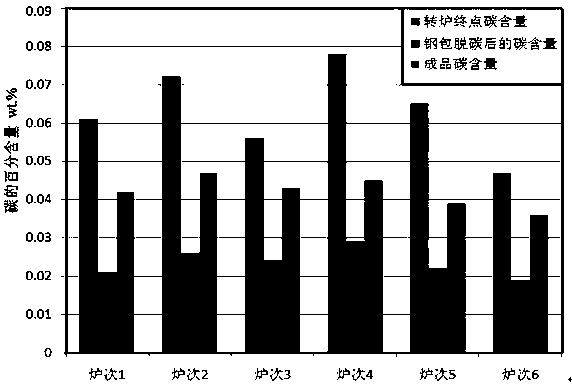
[0018] The molten iron is pretreated before entering the converter. After the treatment, the sulfur content of the molten iron is [S]=0.013%, and the temperature is 1298 °C. Before the molten iron enters the converter, the slag from the pretreatment of the molten iron is removed. After the first furnace before BOF smelting, empty out the remaining steel residue in the BOF, add molten iron and steel scrap to BOF smelting, 136t of molten iron, 15t of scrap steel, the carbon content in the molten iron is 4.86%, and the Si content is 0.46%.

[0019] The converter smelting process is controlled in accordance with conventional requirements for steel grades. The end point temperature of the converter is 1628 °C, the end point oxygen content is 530 ppm, and the end point carbon content is 0.076%. 5min, during the tapping process, pour 200kg of lime into the ladle, and 300kg of refined synthetic slag. No deoxidation and alloying operations are performed during tapping. After tapping, th...

Embodiment 2

[0021] The molten iron is pretreated before entering the converter. After the treatment, the sulfur content of the molten iron is [S]=0.012%, and the temperature is 1295 °C. Before the molten iron enters the converter, the pretreated slag is removed. After the first furnace before BOF smelting, empty the residual steel residue in the BOF, add molten iron and steel scrap for BOF smelting, 133t of molten iron, 16t of scrap steel, the carbon content in the molten iron is 4.67%, and the Si content is 0.44%.

[0022] The converter smelting process control is operated according to the conventional steel grades. The end point temperature of the converter is 1636 ℃, the end point oxygen content is 546 ppm, and the end point carbon content is 0.065%. The tapping time is 5 minutes. During the tapping process, 230 kg of lime and 310 kg of synthetic slag are poured into the ladle. No deoxidation and alloying operations are performed during tapping. Large argon gas stirring operation is per...


PUM


Abstract

The invention discloses a decarburization technological method after the treatment of a converter. In the converter smelting process, control is carried out according to the normal operation technology of the type of steel, appropriate control is carried out on the oxygen and carbon in the steel at the converter terminal, the defined amount of suitable slag materials are added in the process of converter tapping, the suitable oxygen content in the molten steel in a ladle is guaranteed without adding any deoxidization alloy nor carrying out alloying, and no roughing slag is not allowed to existduring tapping. After tapping is completed, molten steel is decarburized with big argon stirring carried out on the ladle, the defined amount of deoxidization alloy is added into the ladle for deoxidization and alloying after the carbon content in the steel is smaller than or equal to 0.03%, and then the ladle is lifted to a refining station for refining operation to obtain the ultra-low carbon steel with the carbon content no larger than 0.05%.

Description

technical field [0001] The invention belongs to the technical field of iron and steel smelting, and in particular relates to a post-converter decarburization process for steel grades with a finished product carbon content lower than 0.05%. Background technique [0002] With the rapid development of all walks of life and the continuous improvement of technology, the composition design of many steel types is also constantly optimized, especially for many low-alloy high-strength steel types. , and the carbon segregation in the steel is more serious when the carbon content is high, which further deteriorates the performance of the steel. Therefore, when designing the composition of this type of steel, the weldability and corrosion resistance of the steel can be improved by increasing the content of alloying elements while reducing the content of carbon. At present, more and more steel types control the carbon content below 0.05% in composition design, which significantly increa...

Claims


Application Information

Patent Timeline
IPC IPC(8): C21C7/068C21C7/06C21C7/00
CPCC21C7/0006C21C7/06C21C7/068
Inventor 杨俊罗登蒋凌枫何航杨勇彭光建
Owner HUNAN VALIN XIANGTAN IRON & STEEL CO LTD
Learn More