
Vehicle body parts manufacturing method

A manufacturing method and component technology, applied in the field of manufacturing high-strength car body parts by hot stamping, to achieve the effect of preventing deviation and free design

Active Publication Date: 2020-06-26
明信汽车科技株式会社 +1
View PDF10 Cites 0 Cited by
  • Summary
  • Abstract
  • Description
  • Claims
  • Application Information

AI Technical Summary

Problems solved by technology

Moreover, tailor rolled blanks are all manufactured by smelters. Therefore, there are certain limitations when applied to the manufacture of a large number of vehicle parts.

Method used


Image

  • Vehicle body parts manufacturing method
  • Vehicle body parts manufacturing method
  • Vehicle body parts manufacturing method

Examples


Embodiment Construction

[0038] The present invention will be described in detail below with reference to the accompanying drawings of the present invention. For the convenience of description, the same constituent elements or components in the drawings use the same reference signs as much as possible.

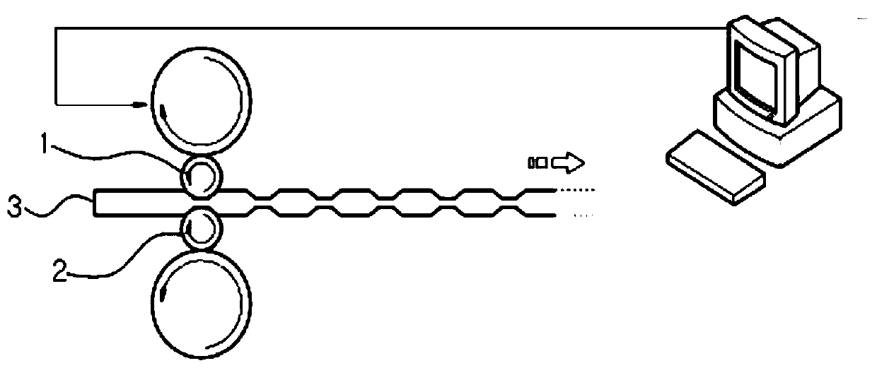
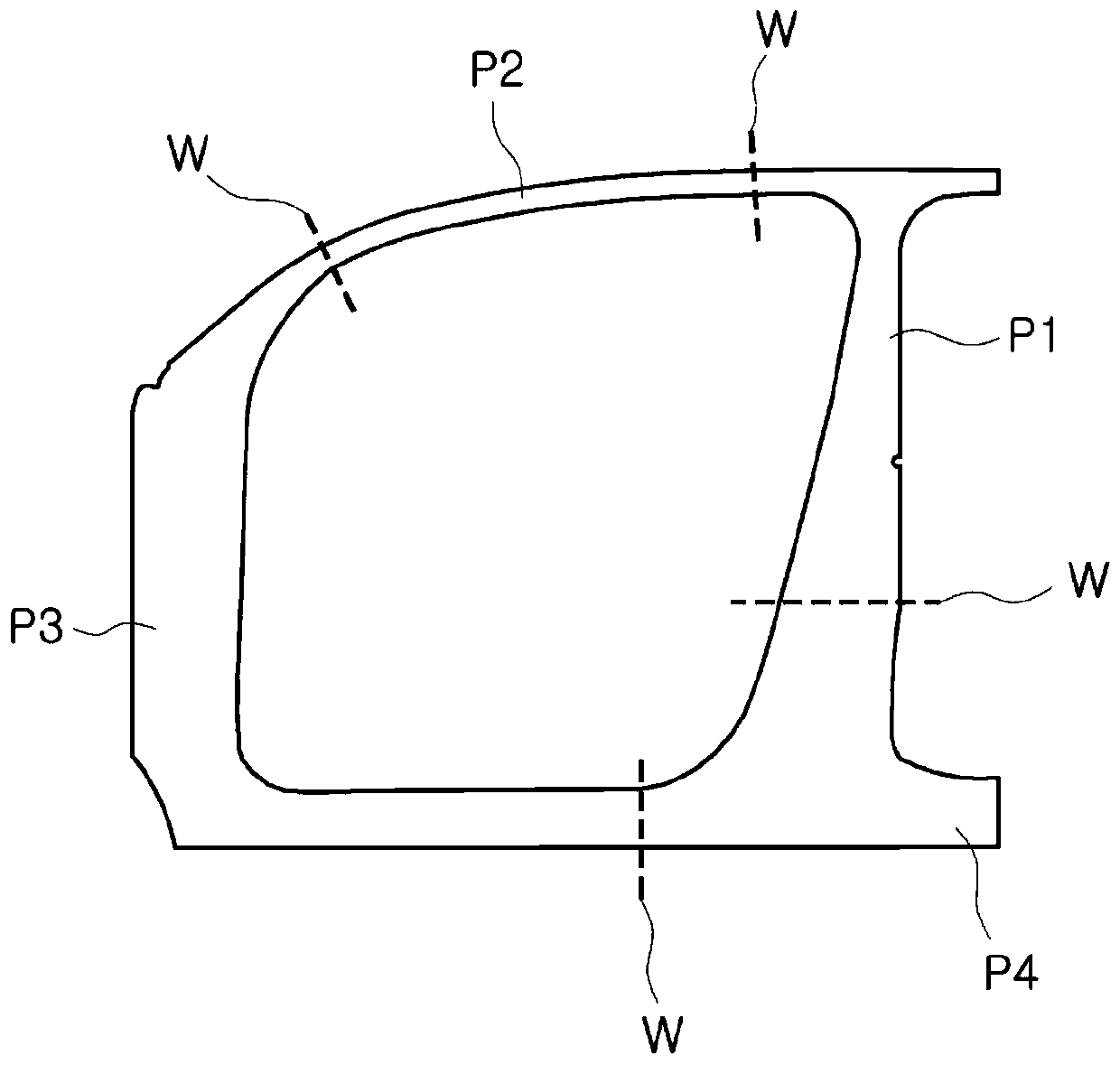
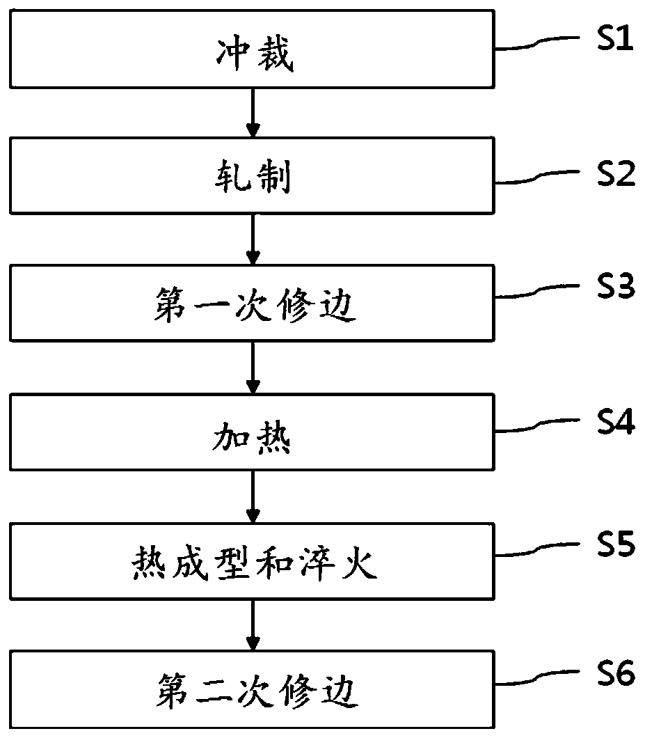
[0039] refer to Figure 3 to Figure 4d , the method of manufacturing a vehicle body member according to the embodiment will be described.

[0040] Such as image 3 As shown, according to the embodiment, the car body parts can be punched (S1), rolled (S2), trimmed for the first time (S3), heated (S4), thermoformed and cooled (S5), trimmed for the second time edge (S6) and manufacture. As a material of the slab 10, an aluminized steel sheet for hot stamping can be used. The aluminum coating of the steel sheet may include an outer aluminum or aluminum alloy layer and an inner intermetallic alloy layer.

[0041] Punching process (S1)

[0042] Such as Figure 4aAs shown, for stamping, aluminized s...


PUM


Abstract

A method for manufacturing car body components is introduced, the steps of which include: rolling a coated slab into two or more regions with mutually different thicknesses; trimming the rolled slab; The slab after the edge is subjected to the steps of hot pressing and cooling. The slab to be rolled has absorption holes and a protrudingly formed flange on the edge region of the slab corresponding to the location of the absorption holes. The slab is rolled in two or more mutually different directions.

Description

technical field [0001] The present invention relates to vehicle body components related to collisions, in particular to a method for manufacturing high-strength vehicle body components by hot stamping. Background technique [0002] One of the biggest topics in the automotive industry is light weight and high strength, and hot stamping technology occupies the center of this topic. British Patent No. 1490535 introduces technology related to hot stamping technology and materials. [0003] Hot stamping is the process of heating a steel plate to a high temperature of 900 to 950°C and then quenching it while forming it under pressure to manufacture high-strength, lightweight parts. The hot stamping material contains about 0.2% by weight of carbon and uses boron steel using manganese element and boron element B for improving heat treatment performance. [0004] This hot stamping can perform forming and heat treatment at the same time, so it not only has excellent production effic...

Claims


Application Information

Patent Timeline
Patent Type & Authority Patents(China)
IPC IPC(8): B23P15/00
CPCB23P15/00B21D35/006B21D22/022C21D1/18C21D8/00C21D2261/00B21D53/88C21D2211/008B21D37/16B21D43/28B23K26/38B21D47/00
Inventor 金长寿车洪锡杨大灏崔纹硕严原益
Owner 明信汽车科技株式会社
Learn More