Buffer device with punching ejection for vehicle body punching machine

A buffer device, a technology of automobile body, applied in the field of body stamping production, can solve the problems of strong bouncing, impact and vibration, loud noise, low production efficiency of stamping machine, reduce vibration and noise, ensure operation safety, and high production efficiency Effect

Inactive Publication Date: 2018-06-12
南京南方联成汽车零部件有限公司
View PDF4 Cites 0 Cited by
  • Summary
  • Abstract
  • Description
  • Claims
  • Application Information

AI Technical Summary

Problems solved by technology

[0005] It is manually loaded and picked up, which is easy to cause human fatigue, which is not good for the safety of life and the quality of stamping parts. The manual stamping production method not only has low production efficiency, but also requires high temperature assistance for stamping production, which makes the operator's work more difficult. Safety cannot be effectively guaranteed, which increases production costs
The other is a fully automated production method, which requires a large capital investment in equipment and puts forward higher requirements for the technical quality of operators and maintenance personnel. In addition, in the stamping production of automobile body stamping parts, the hydraulic press suddenly breaks the blanking process at the moment the plate breaks. Unloading and loss of load will cause the load of the workpiece to disappear suddenly, and the liquid compression energy in the oil cylinder and the elastic deformation energy of the fuselage will be released sharply, causing the punch to suddenly lose control at the moment of the plate breaking, and the punch will drop at a very high speed, causing a huge impact on the buffer cylinder. Impact, the stamping machine will not only produce huge and strong bounce, shock and vibration, and a lot of noise, but also cause damage to the stamping machine and mold, seriously affecting the precision and service life of the stamping machine, it is difficult to meet the actual production needs

Method used


Image

  • Buffer device with punching ejection for vehicle body punching machine
  • Buffer device with punching ejection for vehicle body punching machine
  • Buffer device with punching ejection for vehicle body punching machine

Examples


Embodiment Construction

[0032] In order to make the object, technical solution and advantages of the present invention clearer, the present invention will be further described in detail below in conjunction with the accompanying drawings and embodiments. It should be understood that the specific embodiments described here are only used to explain the present invention, not to limit the present invention.

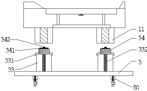
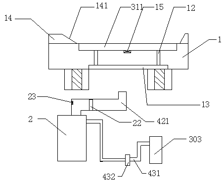
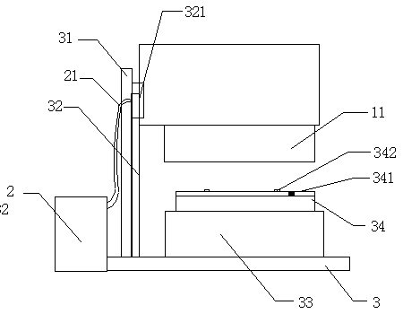
[0033] to combine Figure 1-Figure 4 Shown: Cushioning device for automotive body stamping press with stamping eject, including tooling

[0034] Lower mold 1, cylinder 2, pressure control device 3, roller device 50, cylinder 2 and workbench 3;

[0035]The end of the workbench 3 is fixedly provided with a support column 31, and a slide rail 32 is provided on the support column 31. The front end of the stamping assembly 1 is slidably installed on the slide rail 32 through a slide block 321, and the cylinder 2 is connected to the input end of the slide block 321. , the cylinder 2 is set on the back ...


PUM


Abstract

The invention discloses a buffer device with punching ejection for a vehicle body punching machine. The end part of a workbench is fixedly provided with a supporting column; the supporting column is provided with a sliding rail; the front end of a punching component is installed on the sliding rail through a sliding block in a sliding manner; a cylinder is connected with the input end of the sliding block; a die groove of a lower die of a die is internally provided with pressure punched holes and is provided with a pressure storage chamber through the pressure punched holes; the input end of the pressure storage chamber is connected with the cylinder through a pneumatic pipe; and rolling wheel devices are arranged at the bottom of the workbench. By adopting the buffer device, a punching ejection device and the buffer device are organically combined and mutually matched, so that the problems that bounce, impact and vibration are strong, the noise is large, and the accuracy and the service life difficultly meet the actual production demands in the prior art are solved.

Description

technical field [0001] The invention belongs to the technical field of car body stamping production, and in particular relates to a buffer device for a car body stamping machine with stamping ejection. Background technique [0002] Most of the cold stamping dies are installed on the press, and the deforming force is applied to the sheet placed inside at room temperature to make it deform, so as to obtain a special special tool for product parts of a certain shape, size and performance. In order to improve the wear resistance, hardness and corrosion resistance of the working surface of the mold, heat and surface treatment technology must be adopted. [0003] As far as the car body is concerned, except for some standard parts, almost all of them are welded by sheet metal stamping parts. [0004] There are two existing stamping production methods for automobile body structural parts, one is the traditional manual stamping production method: [0005] It is manually loaded and ...

Claims


Application Information

Patent Timeline
IPC IPC(8): B21D22/00B21D45/04B21D55/00F16F15/02F16F15/023F16F15/04B21D53/88
CPCB21D22/00B21D45/04B21D53/88B21D55/00F16F15/022F16F15/0232F16F15/046
Inventor 李亮李菁华张伟陈朵丁晓青王众王勃
Owner 南京南方联成汽车零部件有限公司
Why Eureka
Try Eureka