Chlorination tail water recycling method and chlorination tail water recycling device

A chlorination tail and water recovery technology, which is applied to calcium carbide feed generators, petroleum industry, acetylene generators, etc., can solve the problems of unreasonable utilization of chlorination tail water, so as to eliminate the impact of odor, eliminate environmental impact, The effect of reducing emissions

Inactive Publication Date: 2018-06-08
重庆市映天辉氯碱化工有限公司
View PDF3 Cites 0 Cited by
  • Summary
  • Abstract
  • Description
  • Claims
  • Application Information

AI Technical Summary

Problems solved by technology

[0004] The first purpose of the present invention is to provide a method for recycling chlorinated tail water, so as to alleviate the technical problem that the chlorinated tail water in the prior art cannot be rationally utilized

Method used


Image

  • Chlorination tail water recycling method and chlorination tail water recycling device
  • Chlorination tail water recycling method and chlorination tail water recycling device
  • Chlorination tail water recycling method and chlorination tail water recycling device

Examples


Embodiment 1

[0038] The method for recycling chlorinated tail water provided by the present invention includes the following steps: S1: injecting chlorinated tail water into the calcium carbide slag slurry concentration tank through the tail water circulation pump; S2: adding trace free chlorine, sulfide Odor gases such as hydrogen and phosphine are reacted and solidified and separated by sedimentation; S3: the supernatant from the calcium carbide slag concentration tank flows into the supernatant tank through the potential difference; S4: the supernatant in the supernatant tank passes through the supernatant pump Sent into the washing and cooling tower; S5: The supernatant is washed and condensed in the washing and cooling tower, and then pumped into the acetylene generator through the slag water recycling pump to react with calcium carbide to produce acetylene gas. There is no need to add industrial water, the amount of water added is reduced, the utilization rate of water is improved, th...

Embodiment 2

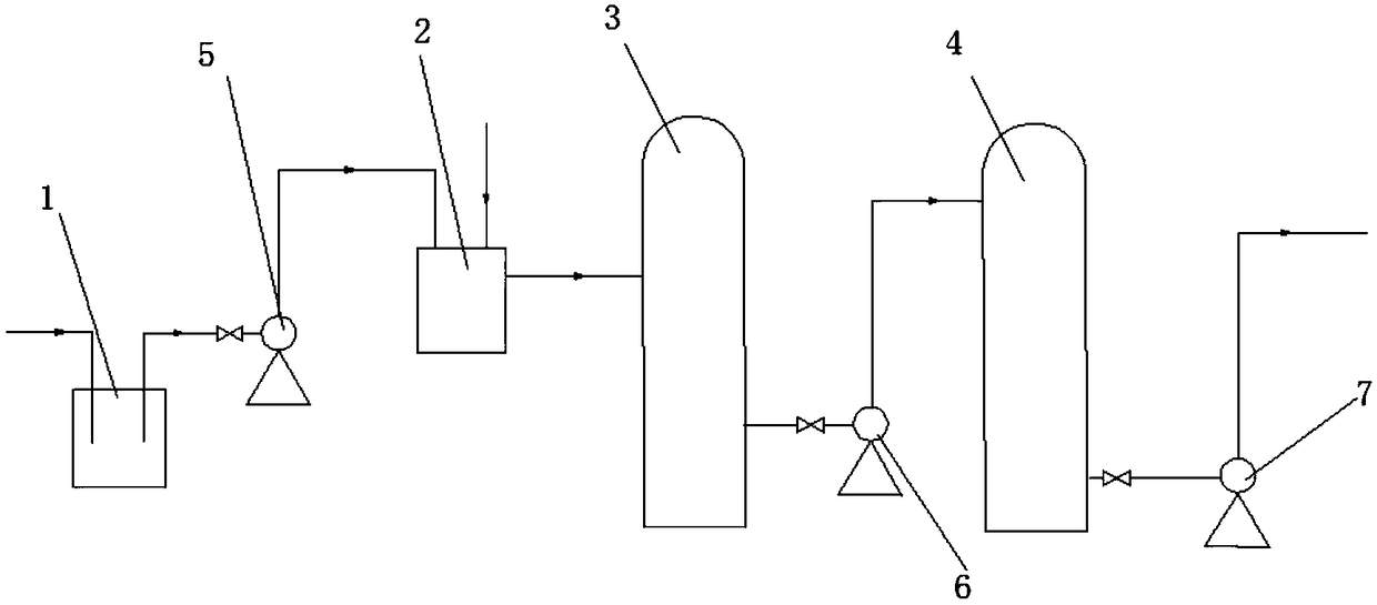
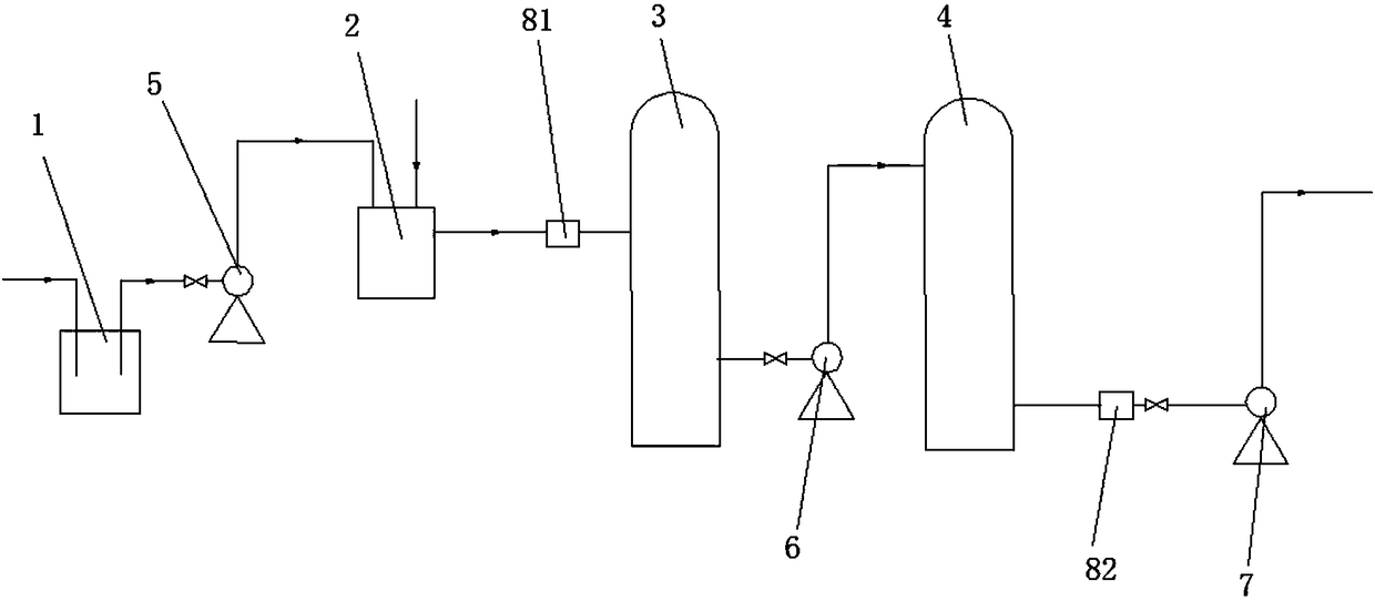
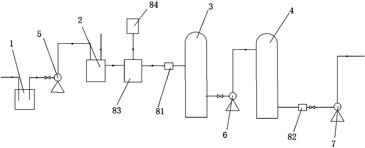
[0050] Such as figure 1 As shown in -4, the chlorinated tail water recovery and utilization device provided by Embodiment 2 of the present invention includes: a chlorinated tail water storage tank 1, a calcium carbide slag concentration tank 2, a supernatant tank 3 and a washing cooling tank connected in sequence through pipelines. Tower 4; a tail water circulation pump 5 is set between the chlorination tail water storage tank 1 and the calcium carbide slag slurry concentration tank 2; a supernatant liquid pump 6 is set between the supernatant liquid tank 3 and the washing cooling tower 4.

[0051] This scheme fully analyzes the properties of each trace impurity in the two waste waters, and uses the principle of redox to transform them into other stable substances through chemical reactions, turning waste water into profit. The specific principles are as follows:

[0052] h 2 S+NaClO=NaCl+S↓+H 2 o

[0053] 2H 3 P+3NaClO=3NaCl+2P↓+3H 2 o

[0054] The chlorinated tail wate...


PUM


Abstract

The invention provides a chlorination tail water recycling method and a chlorination tail water recycling device, and relates to the technical field of chlorination tail water recycling equipment. Thechlorination tail water recycling method comprises the following steps: S1, pumping chlorination tail water into a calcium carbide slag slurry concentration tank by means of a tail water circulatingpump; S2, enabling trace free chlorine, hydrogen sulfide, hydrogen phosphide and other malodorous gases in the calcium carbide slag slurry concentration tank to react so as to be solidified and separated by sedimentation; S3, enabling supernatant in the calcium carbide slag slurry concentration tank to flow into a supernatant tank by means of potential difference; S4, pumping the supernatant in the supernatant tank into a washing cooling tower by means of a supernatant pump; S5, washing and condensing the supernatant in the washing cooling tower, then pumping the supernatant into an acetylenegenerator by means of a slag water reuse pump, and enabling the supernatant to react with calcium carbide so as to produce acetylene gas. The method and the device solve the technical problem that inthe prior art, chlorination tail water can not be reasonably utilized.

Description

technical field [0001] The invention relates to the technical field of chlorinated tail water recycling equipment, in particular to a method for recycling chlorinated tail water and a device for recycling chlorinated tail water. Background technique [0002] The acetylene generator is a device for the reaction of calcium carbide and water to produce acetylene gas. Currently, the water used for acetylene production is mainly the car wash wastewater (containing trace sulfur and phosphorus impurities) generated during the loading of calcium carbide slag. The insufficient part uses fresh primary water, which is consumed every month. Plenty of fresh water at once. [0003] The chlorination tail water is the vacuum absorption waste water from the tail gas of the chlorination tower in the production of trichlorethylene. Because the tail gas contains acid gases such as hydrogen chloride, caustic soda is added to the circulating absorption water for neutralization. The composition o...

Claims


Application Information

Patent Timeline
Patent Type & Authority Applications(China)
IPC IPC(8): C10H15/00
CPCC10H15/00
Inventor 李彬董长江陈红刚杨朝富
Owner 重庆市映天辉氯碱化工有限公司
Why Eureka
Try Eureka