
Heterojunction solar cell and preparation method thereof

A solar cell and heterojunction technology, applied in the field of solar cells, can solve problems such as weakening of solar cell power generation capacity, chipping of cell chips, and increasing ribbon resistance, so as to improve photoelectric conversion efficiency, reduce series resistance, and improve preparation The effect of efficiency

Inactive Publication Date: 2018-06-01
BEIJING JUNTAIINNOVATION TECH CO LTD
View PDF3 Cites 10 Cited by
  • Summary
  • Abstract
  • Description
  • Claims
  • Application Information

AI Technical Summary

Problems solved by technology

However, since the positive and negative poles on the existing battery chip are respectively arranged on the front and back sides of the battery chip, when two adjacent battery chips are arranged, the positive pole of one battery chip is above the battery chip, and the negative pole of the other battery chip is on the top of the battery chip. Below the battery chip, when two battery chips need to be connected in series through a ribbon, one end of the ribbon needs to be connected to the positive pole of one battery chip, and the other end of the ribbon needs to be connected to the negative pole of the battery chip, then the ribbon is connected between the two The position between the battery chips will inevitably be bent, which will easily lead to the fragmentation of the battery chip; and in order to be able to connect the opposite poles on the two battery chips, the size of the welding strip is required to be longer, which undoubtedly increases the resistance of the welding strip , resulting in weakened power generation capability of assembled heterojunction solar cells

Method used


Image

  • Heterojunction solar cell and preparation method thereof
  • Heterojunction solar cell and preparation method thereof
  • Heterojunction solar cell and preparation method thereof

Examples


Embodiment Construction

[0062] Embodiments of the present invention are described in detail below, examples of which are shown in the drawings, wherein the same or similar reference numerals designate the same or similar elements or elements having the same or similar functions throughout. The embodiments described below by referring to the figures are exemplary only for explaining the present invention and should not be construed as limiting the present invention.

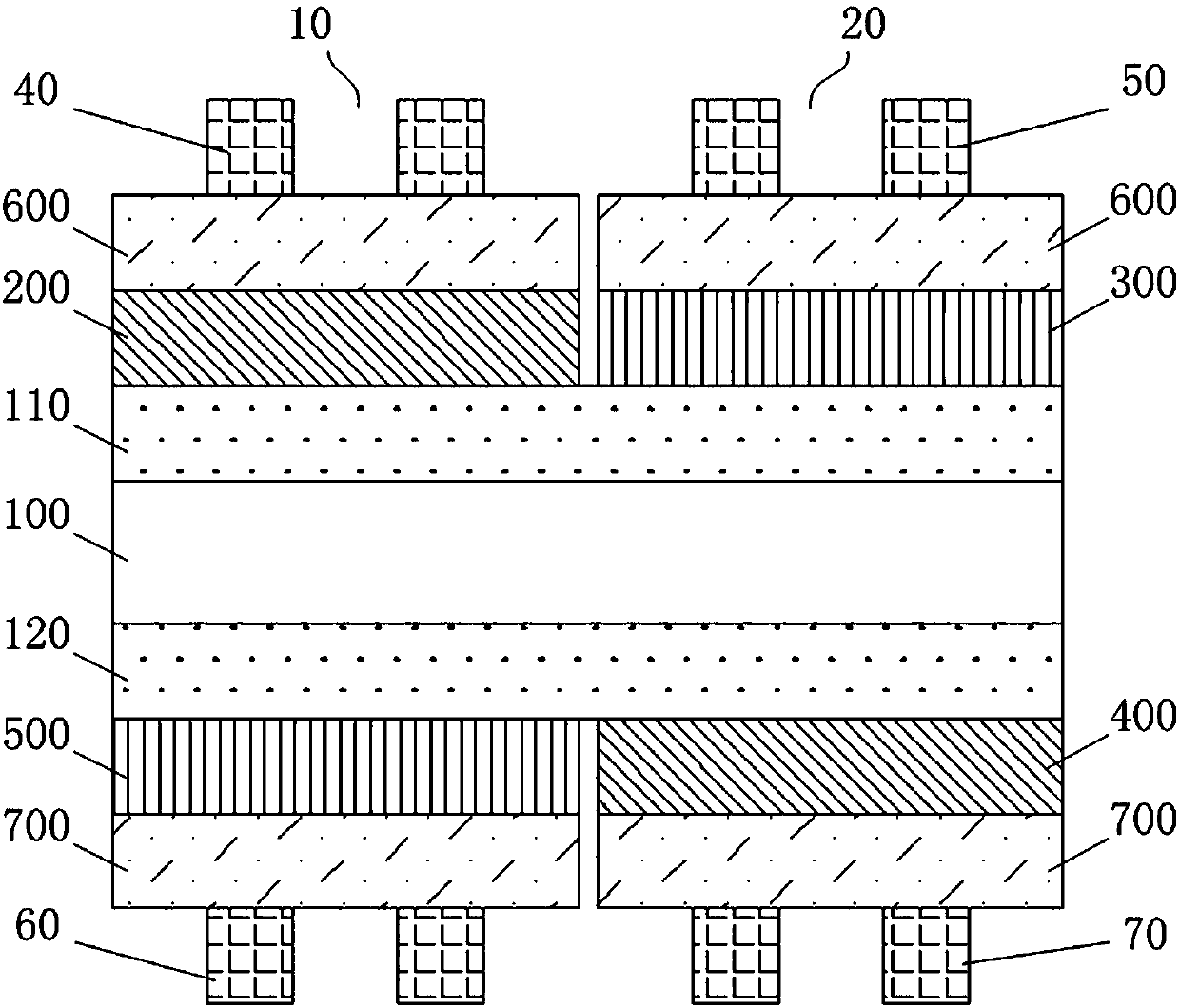
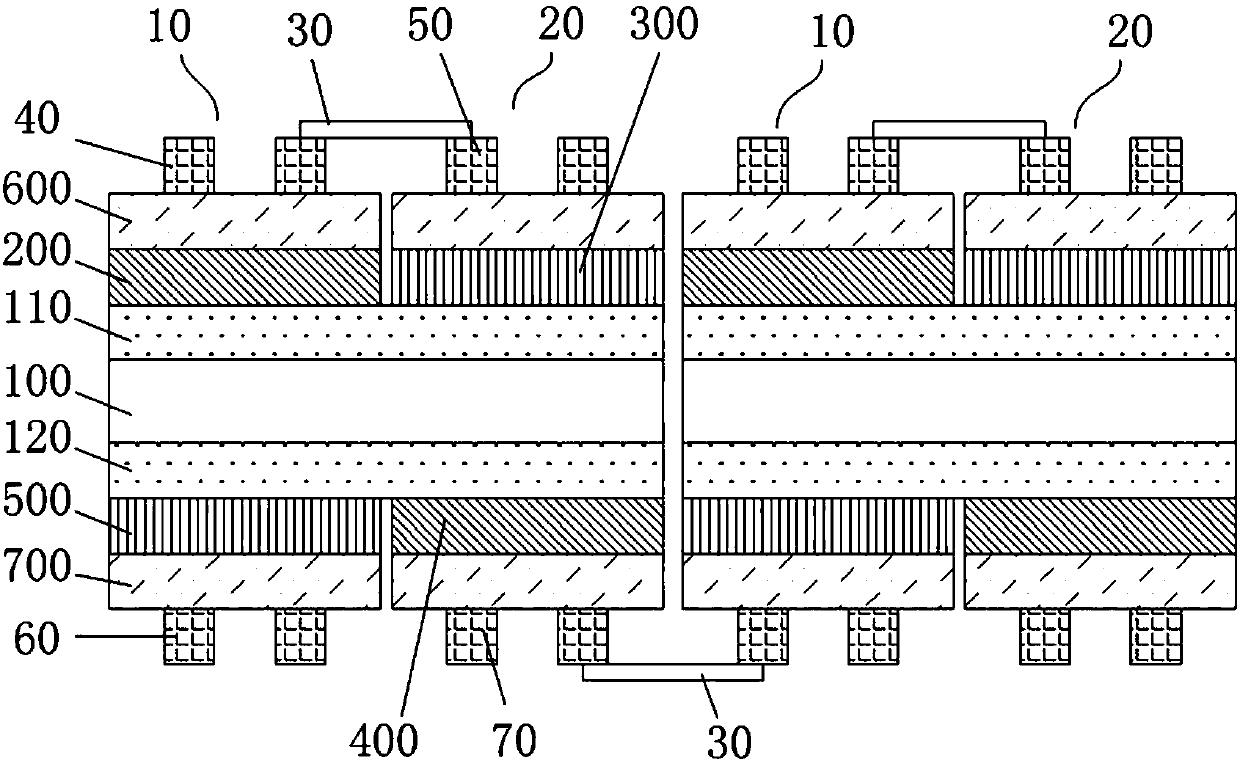
[0063] Please also refer to figure 1 and figure 2 , the embodiment of the present invention provides a heterojunction solar cell, which includes a crystalline silicon substrate 100, a first intrinsic amorphous silicon layer 110 is provided on the front side of the crystalline silicon substrate 100; on the first intrinsic amorphous silicon layer 110 A first N-type amorphous silicon layer 200 and a first P-type amorphous silicon layer 300 are provided; a first negative electrode 40 is provided on the first N-type amorphous silicon layer ...


PUM

PropertyMeasurementUnit
Diameteraaaaaaaaaa

Abstract

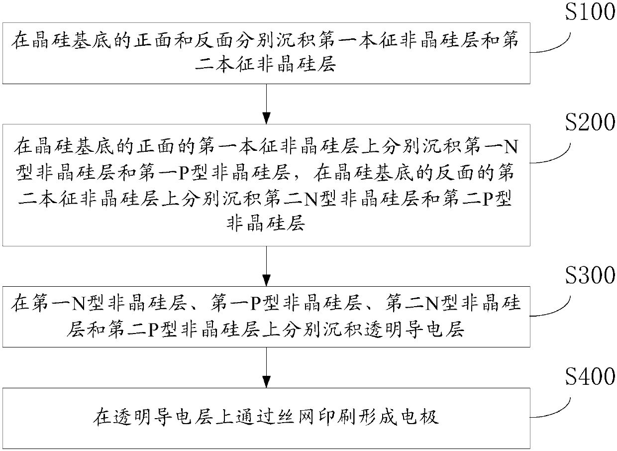
The present invention discloses a heterojunction solar cell and a preparation method thereof, wherein the cell comprises a crystalline silicon substrate, a first intrinsic amorphous silicon layer is arranged on the right side of the crystalline silicon substrate, and a first N-type amorphous silicon layer and a first P-type amorphous silicon layer are arranged on the first intrinsic amorphous silicon layer; a first negative electrode is arranged on the first N-type amorphous silicon layer, and a first positive electrode is arranged on the first P-type amorphous silicon layer; a second intrinsic amorphous silicon layer is arranged on the reverse side of the crystalline silicon substrate and is equipped with a second N-type amorphous silicon layer and a second P-type amorphous silicon layer,a second negative electrode is arranged on the second N-type amorphous silicon layer, and a second positive electrode is arranged on the second P-type amorphous silicon layer. According to the heterojunction solar cell provided by the present invention, by arranging the positive electrodes and the negative electrodes both on the right side and the reverse side of one crystalline silicon substrate, the adjacent two cell chip assemblies can be connected in series by a smaller solder strip, thereby reducing the series resistance, and improving the photoelectric conversion efficiency.

Description

technical field [0001] The invention relates to the technical field of solar cells, in particular to a heterojunction solar cell and a preparation method thereof. Background technique [0002] Silicon-based heterojunction solar cells have excellent power generation performance. Existing silicon-based heterojunction solar cells are usually composed of multiple battery chips connected in series, and adjacent battery chips are connected in series through solder ribbons. However, since the positive and negative poles on the existing battery chip are respectively arranged on the front and back sides of the battery chip, when two adjacent battery chips are arranged, the positive pole of one battery chip is above the battery chip, and the negative pole of the other battery chip is on the top of the battery chip. Below the battery chip, when two battery chips need to be connected in series through a ribbon, one end of the ribbon needs to be connected to the positive pole of one batt...

Claims


Application Information

Patent Timeline
IPC IPC(8): H01L31/05H01L31/0216H01L31/0747
CPCH01L31/02168H01L31/0504H01L31/0747Y02E10/50
Inventor 杨苗郁操徐希翔
Owner BEIJING JUNTAIINNOVATION TECH CO LTD
Learn More