Powder coke multi-layer cyclone circulation coupling microwave auxiliary-heating integrated denitration apparatus
A microwave device and denitrification technology, applied in the field of low temperature denitrification, can solve the problems of high operating cost, no commercial operation cases, and low denitrification efficiency
- Summary
- Abstract
- Description
- Claims
- Application Information
AI Technical Summary
Problems solved by technology
Method used
Image
Examples
Embodiment 1
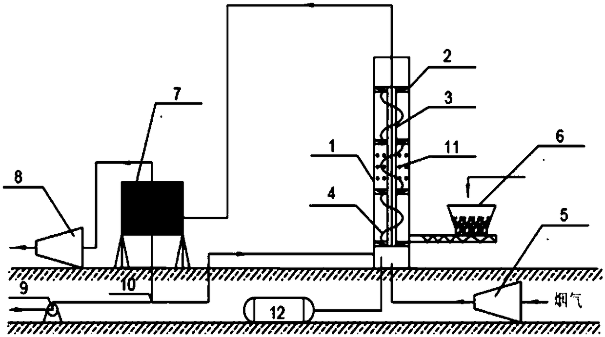
[0034] Embodiment 1: as figure 1 , a built-in center tube multi-layer swirl coupled microwave auxiliary heat integrated denitrification device, mainly including a multi-layer swirl bed with a swirl tube 1, a swirl plate 2, a center tube 3, a guide vane 4, and a booster fan 5 , Screw feeder 6, dust collector 7, induced draft fan 8, centrifugal fan 9, conveyor 10, microwave generator 11, ammonia tank 12. The swirling cylinder 1 is the outer wall of the device, providing a reaction place for the powder coke swirling circulation, and at the same time acting as the outer wall of the swirling flow. The material is related to the composition and temperature of the flue gas, and is generally carbon steel. Guide rotating blades 4 are installed on the outer wall of the central cylinder 3, and the shape is similar to a spiral. The booster fan 5 is connected to the multi-layer swirl bed through pipelines, the screw feeder 6 is connected to the bottom of the multi-layer swirl bed, the am...
Embodiment 2
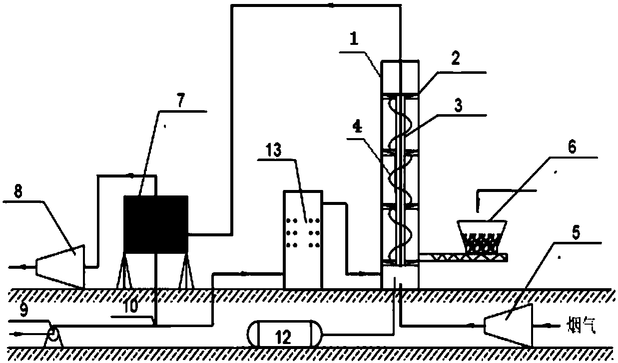
[0038] Embodiment 2: as figure 2 , a powder coke multi-layer swirl circulation coupling microwave regeneration integrated denitrification device, mainly including a multi-layer swirl bed with a swirl tube 1, a swirl plate 2, a central tube 3, a guide vane 4, a booster fan 5, Screw feeder 6, dust collector 7, induced draft fan 8, centrifugal fan 9, conveyor 10, ammonia tank 12, microwave regeneration device 13. The booster fan 5 is connected to the multi-layer swirl bed through pipelines, the screw feeder 6 is connected to the bottom of the multi-layer swirl bed, the ammonia tank 12 is connected to the bottom of the multi-layer swirl bed, the dust collector is located behind the multi-layer swirl bed, and The fan 8 is connected, and the microwave regeneration device 13 is located between the multi-layer swirl bed and the conveyor 10 .
[0039] The process flow is that the nitrogen oxide-containing flue gas enters the multi-layer swirl bed through the booster fan 5, and is mix...
Embodiment 3
[0040] Embodiment 3: as image 3 , an external rotary nozzle coupling microwave auxiliary heat integrated denitrification device, mainly including a multi-layer swirl bed of a swirl cylinder 1 and a swirl plate 2, a booster fan 5, a screw feeder 6, a dust collector 7, and an induced draft fan 8. Centrifugal fan 9, conveyor 10, ammonia tank 12, tangential nozzle 14. The booster fan 5 is connected to the multi-layer swirling bed through pipelines, the screw feeder 6 is connected to the bottom of the multi-layer swirling bed, the ammonia tank 12 is connected to the bottom of the multi-layer swirling bed, and the dust collector is located behind the multi-layer swirling bed, and The fans 8 are connected, the microwave generator 11 is located in the middle layer of the three-layer swirl plates of the multi-layer swirl bed, and the dust collector is located behind the multi-layer swirl bed and is connected with the induced draft fan 8. The tangential nozzles 14 are four layers and si...
PUM
| Property | Measurement | Unit |
|---|---|---|
| Elevation angle | aaaaa | aaaaa |
Abstract
Description
Claims
Application Information
 - R&D
- Intellectual Property
- Life Sciences
- Materials
- Tech Scout
- Unparalleled Data Quality
- Higher Quality Content
- 60% Fewer Hallucinations
Browse by: Latest US Patents, China's latest patents, Technical Efficacy Thesaurus, Application Domain, Technology Topic, Popular Technical Reports.
© 2025 PatSnap. All rights reserved.Legal|Privacy policy|Modern Slavery Act Transparency Statement|Sitemap|About US| Contact US: help@patsnap.com


