
Zero-emission treatment system for desulfurization wastewater from thermal power plants

A technology for thermal power plants and desulfurization wastewater, which is applied in the direction of gaseous effluent wastewater treatment, water/sewage treatment, heating water/sewage treatment, etc. It can solve problems such as increasing flue gas humidity, reducing boilers, and low-temperature corrosion of dust collectors. Reduce emissions, save operating costs, and save costs

Pending Publication Date: 2018-03-23
NORTHWEST BRANCH OF CHINA DATANG CORP SCI & TECH RES INST
View PDF4 Cites 5 Cited by
  • Summary
  • Abstract
  • Description
  • Claims
  • Application Information

AI Technical Summary

Problems solved by technology

The existing way to remove chloride ions is to neutralize the desulfurization wastewater with high-concentration lye and spray it into the flue between the air preheater and the dust collector. 120-128 degrees, spraying liquid into the flue between the air preheater and the dust collector will reduce the temperature of the flue gas discharged from the boiler, causing low-temperature corrosion of the dust collector and affecting its dust removal effect; and under the working condition of 50% BMCR, The temperature of the flue gas discharged from the boiler will be lower, and the low-temperature corrosion of the flue gas pipe and dust collector will be more obvious; in addition, the lye sprayed will increase the humidity of the flue gas in the flue, which is not conducive to the subsequent treatment and discharge of flue gas

Method used


Image

  • Zero-emission treatment system for desulfurization wastewater from thermal power plants

Examples


Embodiment Construction

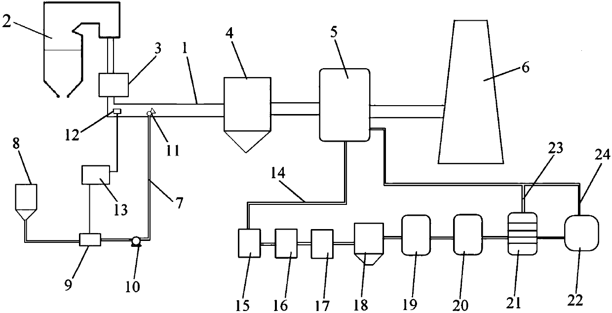
[0032] refer to figure 1 According to the embodiment of the content of the present invention, the zero-discharge treatment system for desulfurization wastewater in thermal power plants includes an air preheater connected in sequence between the flue gas outlet at the tail of the boiler 2 and the flue gas inlet of the chimney 6 through the flue gas pipeline 1 3. The dust remover 4 and the desulfurization absorption tower 5 also include an alkaline substance supply device, a chloride ion concentration detector 12, a controller 13 and a desulfurization waste water recycling device; the alkaline substance supply device communicates with the The flue gas pipeline 1 between the air preheater 3 and the dust remover 4 is connected, and the alkaline supply device includes a dry powder storage tank 8, a weighing machine 9, a blower fan 10 and a powder Nozzle 11, one end of the supply pipeline 7 is a dry powder storage tank 8, the other end of the supply pipeline 7 is a powder nozzle 11,...


PUM


Abstract

The invention discloses a zero-emission treatment system for desulfurization wastewater from thermal power plants. The zero-emission treatment system comprises an air pre-heater, a dust remover, a desulfurization absorption tower, an alkaline substance supply device, a chlorine ion concentration detector, a controller and a desulfurization wastewater recycling device. The air pre-heater, the dustremover and the desulfurization absorption tower are arranged between a boiler and a chimney, the alkaline substance supply device is arranged between the air pre-heater and the dust remover in a communicated manner and comprises a dry powder storage tank, a weighing machine, a fan and a powder spray nozzle, and the powder spray nozzle extends into a flue gas pipeline between the air pre-heater and the dust remover; the chlorine ion concentration detector is arranged at a flue gas outlet end of the air pre-heater; the controller is connected with the chlorine ion concentration detector and theweighing machine; the desulfurization wastewater recycling device comprises a wastewater neutralization basin, a sedimentation basin, a flocculation basin, a clarification basin, an RO (reverse osmosis) machine and an evaporator, and a low-salinity water outlet of the RO machine is communicated with the desulfurization absorption tower. The zero-emission treatment system has the advantages that the content of chlorine ions which are fed into the desulfurization absorption tower can be reduced to a great extent, and accordingly the emission of the desulfurization wastewater can be obviously reduced; the desulfurization wastewater is free of emission.

Description

technical field [0001] The invention belongs to the field of desulfurization wastewater treatment, and in particular relates to a zero-discharge treatment system for desulfurization wastewater of a thermal power plant. Background technique [0002] The root cause of desulfurization wastewater is the recycling of desulfurization slurry, which leads to the enrichment of chloride ions in the desulfurization tower. In order to maintain the balance of the desulfurization tower in the desulfurization system, it is necessary to continuously discharge the desulfurization wastewater in the desulfurization tower and inject new industrial water. Thus a large amount of desulfurization wastewater is produced. Due to high turbidity, high hardness, and high content of heavy metals and chloride ions, desulfurization wastewater is easy to scale and corrode, and it is difficult to treat. The desulfurization wastewater has a large amount of treatment and poor water quality, which cannot meet t...

Claims


Application Information

Patent Timeline
Patent Type & Authority Applications(China)
IPC IPC(8): C02F9/10B01D53/14B01D53/68B01D53/83C02F103/18
CPCB01D53/1425B01D53/346B01D53/685C02F9/00C02F1/04C02F1/66C02F1/62C02F1/441C02F1/52C02F2103/18C02F2001/427B01D2258/0283B01D2257/30
Inventor 郭静娟马强黄鑫邓悦
Owner NORTHWEST BRANCH OF CHINA DATANG CORP SCI & TECH RES INST
Learn More