Hole bottom fixing device of deformed measuring rod in rock borehole

A fixing device and a technology in the borehole, which is applied in the field of geotechnical engineering, can solve the problems of poor anti-corrosion ability of the fixing device, resistance to groundwater corrosion, limited anti-vibration ability of fixing claws, etc., to achieve reliable long-term anchoring anti-vibration and improve anti-corrosion performance, reliable corrosion resistance

Inactive Publication Date: 2018-03-20
INST OF ROCK AND SOIL MECHANICS - CHINESE ACAD OF SCI
View PDF15 Cites 1 Cited by
  • Summary
  • Abstract
  • Description
  • Claims
  • Application Information

AI Technical Summary

Problems solved by technology

[0004] However, the fast fixing equipment or technical reserves at the bottom of the drilling hole for measuring rods suitable for on-site deformation monitoring are insufficient, and there are only several traditional measuring rods in the rock mass drilling. Fixing devices or methods need to be improved:
[0005] (1) Traditional anchoring agent / slurry fixation: The displacement meter fixing method that is often used to measure the internal deformation of the rock mass is to install the displacement meter inside the borehole and then perform the anchoring agent consolidation treatment, and wait for the anchoring agent / slurry to pass through. After a period of hardening, the measuring rod can be fixed at the bottom of the borehole. Although this method of directly injecting the agent / slurry has the advantages of high reliability, it also has disadvantages: on the one hand, it takes a certain time for the slurry to solidify, which leads to The measurement lags behind for a period of time, which makes it impossible to start the monitoring of surrounding rock deformation as soon as possible; on the other hand, no technical means are used to ensure that the measuring rod is located in the center of the borehole, which may easily lead to certain measurement errors or poor anchoring effect between the measuring rod and the hole wall. Ideal (Chinese patent application number 201120070270.1, the patent name is "Sealing and sealing device for grouting installation of multi-point displacement meter for rock and soil body measurement", the grouting installation of multi-point displacement meter in this application adopts the method of grouting sealing hole sealing, its It takes time for grouting to consolidate; Chinese patent application number 201310237358.1, the title of the invention is "a multi-point displacement gauge installation buried grouting method", the application provides a displacement gauge using double grouting, that is, the displacement gauge is equipped with Root exhaust pipe, distal anchor head and proximal anchor head, and double grouting pipes solve the problem of full grouting, but do not consider how to place the measuring rod in the center of the borehole; Chinese patent application number 201320343285.X, invention Name "a vertical multi-point displacement meter device for geotechnical engineering safety monitoring", the application proposes that the first grouting pipe in the displacement meter is installed one meter inside the orifice, and the second grouting pipe is installed at the far end At the anchor head, the exhaust pipe is one meter beyond the distal anchor head, and several side holes are drilled within 20cm from the top of the exhaust pipe. Consider whether the displacement gauge is offset at the drilling position)
[0006] (2) Widely used mechanical fixation: currently widely used mechanical locking rod / rod end fixation device based on the principle of friction and anti-slip, because its fixing effect directly depends on the friction performance between the mechanical device and the drilling rock surface and The locking force interacts, so its anti-vibration ability is poor, and it is easy to loosen due to the blasting vibration of underground engineering construction; moreover, the anti-corrosion ability of the fixing device is poor in the wet and water-rich environment of the underground rock mass, and the reliability of its long-term fixing effect is not high Therefore, it is necessary to consider the anti-corrosion measures of the fixing device itself (Chinese patent application number 200920085585.6, the patent name is "deep hole multi-point displacement measurement point fixing device", the application discloses a deep hole displacement measurement point fixing device, By piercing through the indium steel wire hole of the anchor head at the measuring point and fixing it with fixing screws, the device has no corrosion resistance; Chinese patent application number 201310024219.0, the patent name is "Multi-point displacement meter installation method and device for detecting deep displacement of surrounding rock" , the application draws out the hollow tube at one time, so that the fixing device pops out from the tube in situ, and the displacement gauge is fixed on the hole wall, and its anchoring force is limited and it is not resistant to groundwater corrosion; Chinese patent application number 201510411603.5, the patent name is "a kind of Anchor Device for Multi-point Displacement Meter in Drilling Hole", this application adopts the design of tapered plunger and fixed claw located at the right end of the circular tube to realize the anchoring of displacement meter, but the anti-vibration ability of the fixed claw is limited; Chinese patent application No. 201410705835.7, the patent name is "A Folding Blade Type Multi-point Displacement Gauge Anchor Head", the application proposes a folding blade type multi-point displacement gauge anchor head for measurement in soft soil areas, by shrinking the previously folded blade Inside the bottom frame, it is opened during installation to realize anchorage, which has certain limitations in its practicality in rock underground engineering; It is proposed to use a tubular compressed wood sleeve to achieve expansion and friction fixation in the displacement transmission steel wire casing. Obviously, its long-term durability and anti-vibration problems need to be improved.

Method used


Image

  • Hole bottom fixing device of deformed measuring rod in rock borehole

Examples


specific Embodiment

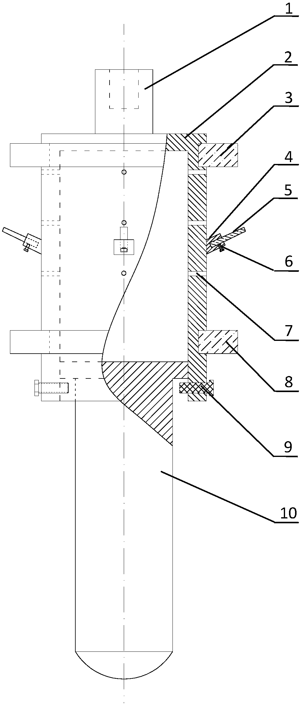
[0027] (1) Measure the outer diameter D of the first stopper 3 of the device 0 =78mm, so this kind of drilling is designed to drill the hole diameter D 1 =76mm, the elastic spines 5 are loaded into the spine seat 4, and the position of the elastic spines 5 in the inner hole of the spine seat 4 is adjusted through the fixing screw 6, so that the distance L between the outer endpoints of the two elastic spines 5 arranged symmetrically at 180° 1 is 90mm.

[0028] (2) The length of the inner cavity of the slurry-holding chamber 2 is measured to be 400 mm, and the test shows that the exposed length of the piston push rod 10 at the lowermost end of the slurry-containing cavity 2 is greater than that when the piston push rod 10 is pushed to the uppermost end surface of the slurry-containing cavity 2 length.

[0029] (3) Before the fixing device is placed on site, use paraffin to block the twelve slurry discharge holes 7 of the slurry chamber 2, and then release the clamping screw 9...


PUM

PropertyMeasurementUnit
diameteraaaaaaaaaa

Abstract

The invention discloses a hole bottom fixing device of a deformed measuring rod in a rock borehole, and belongs to the technical field of geotechnical engineering. The fixing device is composed of a connecting rod, a grout containing cavity body, a first grout stopping plug, elastic ratchets, a second grout stopping plug and a piston pushing rod; the connecting rod is fixedly connected to the upper end surface of the grout containing cavity body, the first grout stopping plug and the second grout stopping plug are embedded into the upper portion and the lower portion of the annular outer wallsurface of the grout containing cavity body respectively, three rows of grout discharging through holes are formed in the grout containing cavity body, ratchet bases are fixedly connected to the outerside of the grout containing cavity body, the elastic ratchets are fixed to the ratchet bases through fixing threaded rods, clamping threaded rods are arranged at the lower end of the grout containing cavity body, and the distance between the outermost ends of the two elastic ratchets symmetrically distributed is larger than the outer diameter of the second grout stopping plug. The hole bottom fixing device has the advantages that installation is fast, grouting is automatically conducted, the deformed measuring rod is reliably fixed to the central position of the borehole, vibration resistance of long-term anchorage is high and corrosion resistance is good, and the device is applicable to fixation of the deformed measuring rod for an underground construction rock.

Description

technical field [0001] The invention relates to a hole bottom fixing device for a deformation measuring rod in a rock mass borehole, and more particularly relates to a fixing device for quickly installing a measuring rod at the bottom of a drilling hole when the deformation measurement of an underground engineering surrounding rock mass is performed, belonging to rock and soil field of engineering technology. Background technique [0002] With the rapid development of society and economy, many large-scale underground projects will be built in the construction of national infrastructure. The monitoring of surrounding rock deformation after the excavation of underground tunnels / tunnels / stopes is very important for engineering safety analysis and disaster warning. Important: (1) In terms of water resources development and utilization, nearly 40 1 million kW hydropower stations will be built or included in the planning in China, and large underground powerhouses and water pipeli...

Claims


Application Information

Patent Timeline
Patent Type & Authority Applications(China)
IPC IPC(8): E21B47/00
CPCE21B47/00
Inventor 江权刘畅张妹珠冯夏庭苏国韶杨冰
Owner INST OF ROCK AND SOIL MECHANICS - CHINESE ACAD OF SCI
Why Eureka
Try Eureka