
Dual-mode band-pass filter with compact structure

A compact, filter technology, applied in waveguide-type devices, electrical components, circuits, etc., can solve the problems of poor out-of-band characteristics, insufficient compactness, and high processing costs, achieve good out-of-band rejection characteristics, and maintain dual-mode characteristics. , the effect of reducing the operating frequency

Inactive Publication Date: 2018-03-13
CHENGDU UNIV
View PDF10 Cites 2 Cited by
  • Summary
  • Abstract
  • Description
  • Claims
  • Application Information

AI Technical Summary

Problems solved by technology

[0003] The existing dual-mode bandpass filter has the following defects and deficiencies: (1) The size of the filter is large and not compact enough; (2) The passband characteristics are not good; (3) The bandwidth of the passband is narrow; (4) The out-of-band characteristics are not good and the selectivity is not high; (5) The structure is complex and the processing cost is high

Method used


Image

  • Dual-mode band-pass filter with compact structure
  • Dual-mode band-pass filter with compact structure

Examples


Embodiment Construction

[0015] Further describe the technical scheme of the present invention in detail below in conjunction with accompanying drawing:

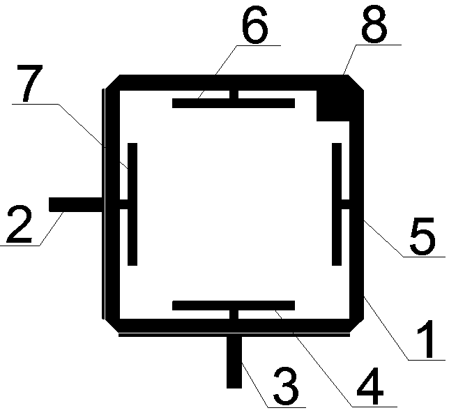
[0016] Such as figure 1 As shown, a compact dual-mode bandpass filter includes a dielectric substrate, a metal ground plate positioned on the lower surface of the dielectric substrate, and a filter structure positioned on the same plane as the upper surface of the dielectric substrate; the filter structure includes Ring resonator 1, T-shaped input feeder 2, T-shaped output feeder 3, four T-shaped loads 4~7 and perturbation sheet 8;

[0017] The T-shaped input feeder 2 and the T-shaped output feeder 3 have the same structure, and both include a 50Ω microstrip line and parallel branches vertically connected to the 50Ω microstrip line; the perturbation sheet 8 is located inside the ring resonator 1 At the corner formed by two of the sides, the T-shaped input feeder 2 and the T-shaped output feeder 3 are located outside the ring resonator 1, and the r...


PUM

PropertyMeasurementUnit
Thicknessaaaaaaaaaa
Electrical lengthaaaaaaaaaa

Abstract

The invention discloses a dual-mode band-pass filter with a compact structure. The dual-mode band-pass filter comprises a dielectric substrate and a filter structure positioned on the upper surface ofthe dielectric substrate on the same plane; the filter structure comprises annular resonator (1), T-shaped input feeder line (2), a T-shaped output feeder line (3), four T-shaped loading parts (4-7)and a infinitesimal disturbance sheet (8); the T-shaped loading parts (4-7) are positioned in the annular resonator (1), and each of the T-shaped loading parts comprises a parallel part and a perpendicular part perpendicularly connected with the parallel part; the parallel part of each of the T-shaped loading parts (4-7) is parallel to one edge of the annular resonator (1) separately; and the perpendicular part of each of the T-shaped loading parts (4-7) is connected to the midpoint position of one edge of the annular resonator (1) separately. By virtue of the dual-mode resonator with the T-shaped loading parts, the dual-mode characteristic can be realized, and a relatively large passband bandwidth range is achieved; and in addition, working frequency can be lowered effectively, and miniaturization of the dual-mode band-pass filter can be realized.

Description

technical field [0001] The invention relates to the field of microwave devices, in particular to a compact dual-mode band-pass filter. Background technique [0002] With the development of wireless communication systems, higher requirements are put forward for microwave filters, and high performance and miniaturization are the future development trends. In the miniaturization design of microwave filters, planar dual-mode bandpass filters have received more attention due to their high performance and compact structure. Dual-mode resonators are widely used in the design of dual-mode bandpass filters. Each dual-mode resonator can be regarded as a dual-frequency tuning circuit, that is, one resonator can generate two resonance frequencies at the same time. Therefore, For n-order filters, when dual-mode resonators are used, the number of resonators is reduced by half compared with single-mode, so that the size of the circuit can be effectively reduced. [0003] The existing dua...

Claims


Application Information

Patent Timeline
IPC IPC(8): H01P1/203
CPCH01P1/20381
Inventor 高山山乔惠民
Owner CHENGDU UNIV
Learn More