
Bi-directional galvonometric scanning and imaging

a bi-directional scanning and imaging technology, applied in the field of galvanometric bi-directional scanning and imaging devices, can solve the problems of acoustic noise generated by the scanning device becoming a problem, contamination more readily forming on the rotating polygonal mirror, and relatively expensive air or other fluid bearings, etc., and achieves low operating frequency and high scan efficiency.

Inactive Publication Date: 2005-03-22
LEXMARK INT INC
View PDF25 Cites 33 Cited by
  • Summary
  • Abstract
  • Description
  • Claims
  • Application Information

AI Technical Summary

Benefits of technology

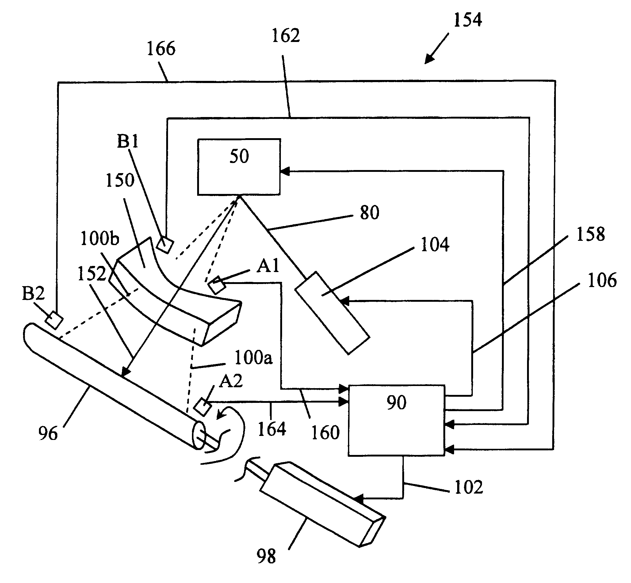
The present invention addresses these problems by providing a scanning device and method with control and monitoring that is capable of operating in the unstable environment of a resonant oscillator yet provides for bi-directional scanning operation, relatively high scan efficiency and relatively low operating frequencies for a particular application. In particular, the control system is capable of locating an imaging window in both scan directions and controlling the flow of data depending on the scan direction and the location in the scan.

Problems solved by technology

A polygonal mirror scanning device requires relatively expensive air or other fluid bearings to ensure reliable performance of the scanning device as the rotational speed of the polygonal mirror increases to achieve higher print speeds.
Additionally, as rotational speed of the polygonal mirror increases, acoustic noise generated by the scanning device becomes a problem and contamination forms more readily on the rotating polygonal mirror.
Also, power consumption increases proportionally with the square of the rotational speed of the polygonal mirror.
Despite these problems, high precision scanning devices employing mirrors remain dominant in the field primarily because of problems with other technologies.
In the case of scanning devices using galvanometric oscillators, the problems include relatively low scan efficiency, relatively high laser modulation frequencies, scan speed instability, scan amplitude instability, and resonant frequency instability associated with environment.

Method used


Image

  • Bi-directional galvonometric scanning and imaging
  • Bi-directional galvonometric scanning and imaging
  • Bi-directional galvonometric scanning and imaging

Examples


Embodiment Construction

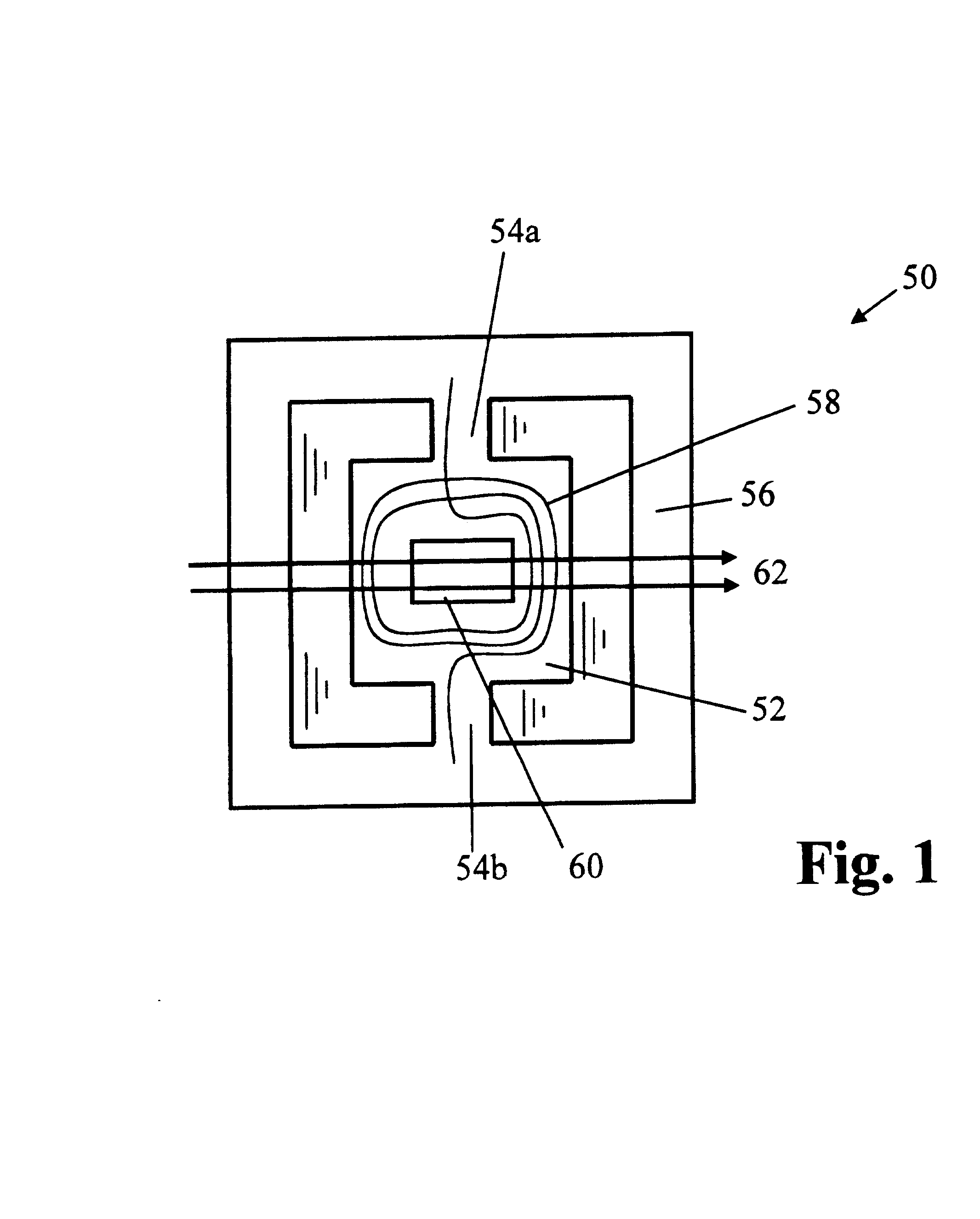
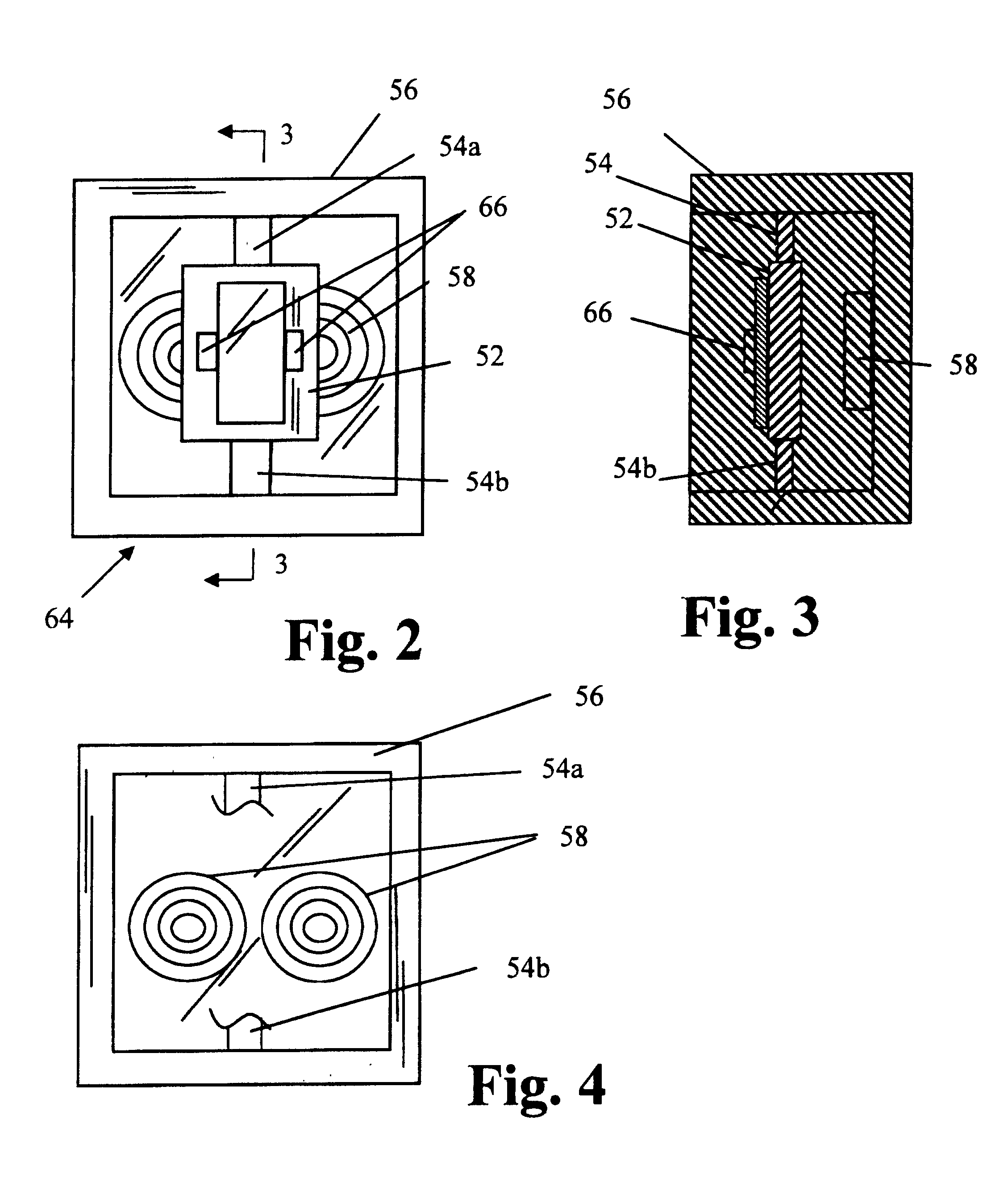
Preferred embodiments of the present invention utilize a torsion oscillator. The torsion oscillator 50 of FIG. 1 comprises a central generally rectangular plate 52 suspended by two extensions 54a, 54b of the material of plate 52. The plate 52 is generally symmetrical about its axis of oscillation. Extensions 54a, 54b are integral with a surrounding frame 56. Typically, the plate 52, extensions 54a, 54b and frame 56 are cut or etched from a single silicon wafer. A coil 58 of conductive wire and a mirror 60 or similar reflective surface are placed on the central plate. The mirror may be a smooth or polished surface on the silicon plate 52, since silicon itself is about sixty percent reflective Typically the mirror is a deposited layer of gold (or other material) on the smooth silicon substrate. Since the reflectivity of the silicon is wavelength dependent (falling off rapidly about 1 micron wavelength), a deposited mirror is typically used, or the raw silicon can be used without a mir...


PUM


Abstract

In bi-directional imaging, such as bi-directional printing, a galvanometric oscillator scans a light beam through a scan path across an imaging window. A controller enables transmission of video data to a modulator when the light beam is positioned for imaging on the imaging window. Video data is transmitted to the modulator when the light beam is traveling in a forward direction or a reverse direction across the imaging window, whereby a modulated light beam is capable of producing an image when traveling in the forward or reverse directions.

Description

FIELD OF THE INVENTIONThe present invention relates to galvanometric bi-directional scanning and imaging devices and methods and particularly relates to bi-directional printing utilizing a resonant galvanometric oscillator in a scanning device.BACKGROUND OF THE INVENTIONResonant torsion oscillators are known, but are not typically employed in devices utilizing optical systems such as laser printing devices. Typically in laser printing devices, a scanning polygonal mirror is used for the purpose of scanning a light beam across a latent image storage device such as a photoconductor. A polygonal mirror scanning device requires relatively expensive air or other fluid bearings to ensure reliable performance of the scanning device as the rotational speed of the polygonal mirror increases to achieve higher print speeds. (Generally, print speed is measured in pages per minute (PPM)). Additionally, as rotational speed of the polygonal mirror increases, acoustic noise generated by the scannin...

Claims


Application Information

Patent Timeline
Patent Type & Authority Patents(United States)
IPC IPC(8): B41J2/435B41J2/47
CPCB41J2/47
Inventor BUSH, CRAIG P.CANNON, ROGER S.GREEN, TIMOTHY A.KLEMENT, MARTIN C.
Owner LEXMARK INT INC
Learn More