Eureka AIR delivers breakthrough ideas for toughest innovation challenges, trusted by R&D personnel around the world.

Electronic Control Unit with Power Loss Compensation

Inactive Publication Date: 2009-07-23
HELLA KG HUECK & CO
View PDF2 Cites 32 Cited by
  • Summary
  • Abstract
  • Description
  • Claims
  • Application Information

AI Technical Summary

Benefits of technology

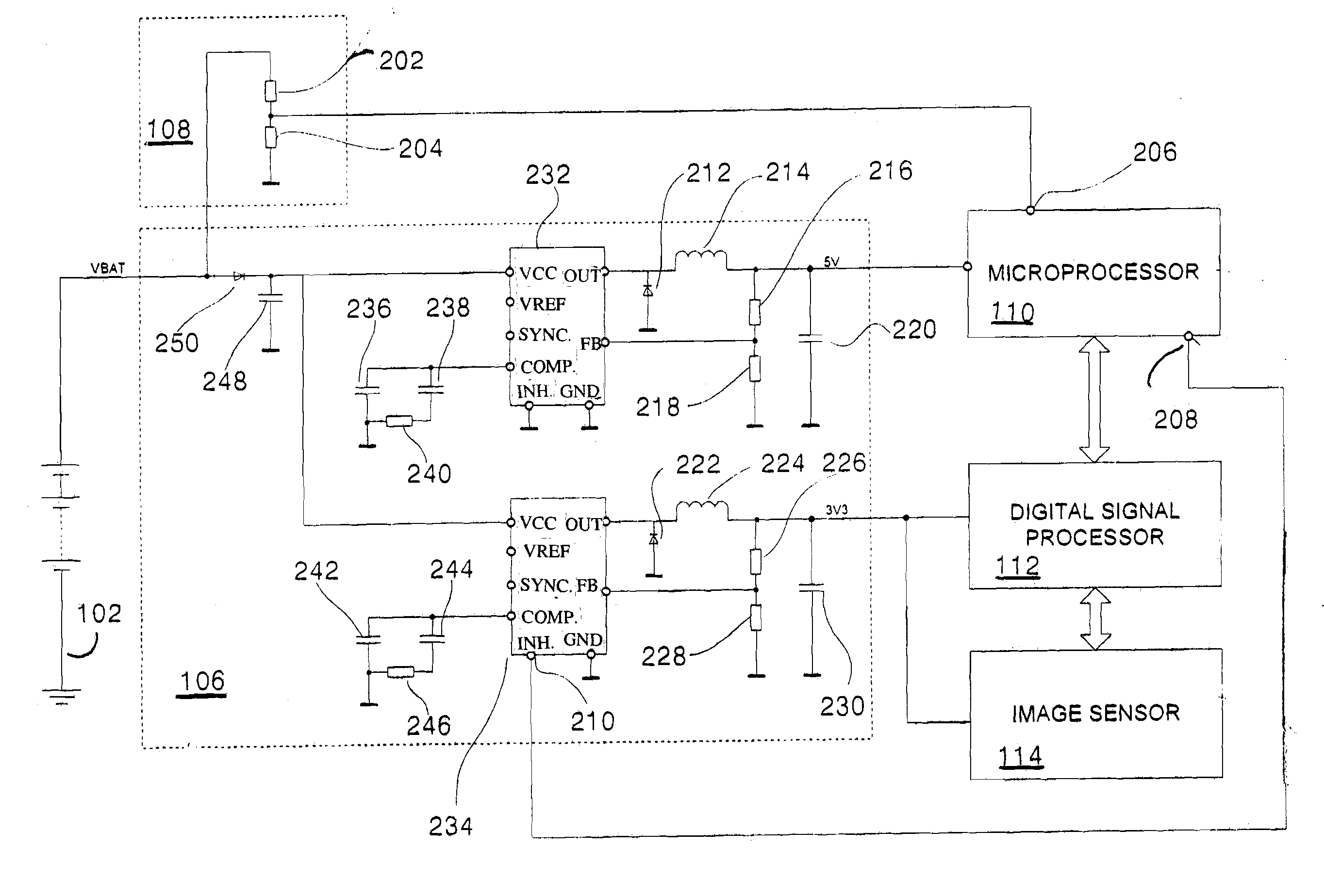
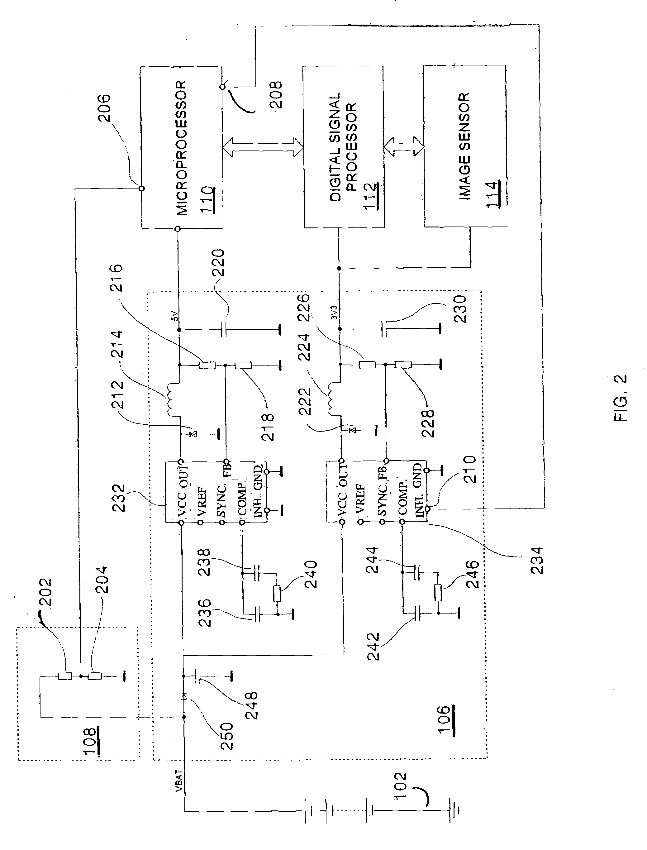
[0013]Both electronic processors are powered by an internal power supply, which is connected to the vehicle battery. Vehicle battery voltage is monitored by a low voltage detection circuit. If the vehicle battery voltage falls below a predetermined value a low-voltage signal is generated. The internal power supply comprises a hold capacitor, which is discharged during external power loss. To maximize the time that can be compensated by the limited energy stored in the hold capacitor, the electronic control unit's power consumption is reduced during external power loss. Power consumption is reduced by switching the second processor into a low current consumption state, such as by turning off the second processor's supply voltage, reducing the second processor's operating frequency, or ordering the second processor into a sleep, deep sleep, or hibernation mode.
[0014]Abruptly turning off the second processor's supply voltage may cause undesirable memory loss, and should be avoided. Therefore the second processor may be turned off with a delay after a low-voltage condition is detected. The low-voltage signal is communicated to the second processor, which responsive thereto prepares for an imminent power loss by saving settings into keep-alive memory. Power to the second processor may be removed with a predetermined delay time sufficiently long for the second processor to save its settings. Alternatively, the second processor may signal that it is ready to shut down.

Problems solved by technology

The electronic processor thereupon disables one or more components within the electronic control unit so that the electronic control unit operates with limited functionality for the duration of external power loss.

Method used


Image

  • Electronic Control Unit with Power Loss Compensation
  • Electronic Control Unit with Power Loss Compensation
  • Electronic Control Unit with Power Loss Compensation

Examples


Embodiment Construction

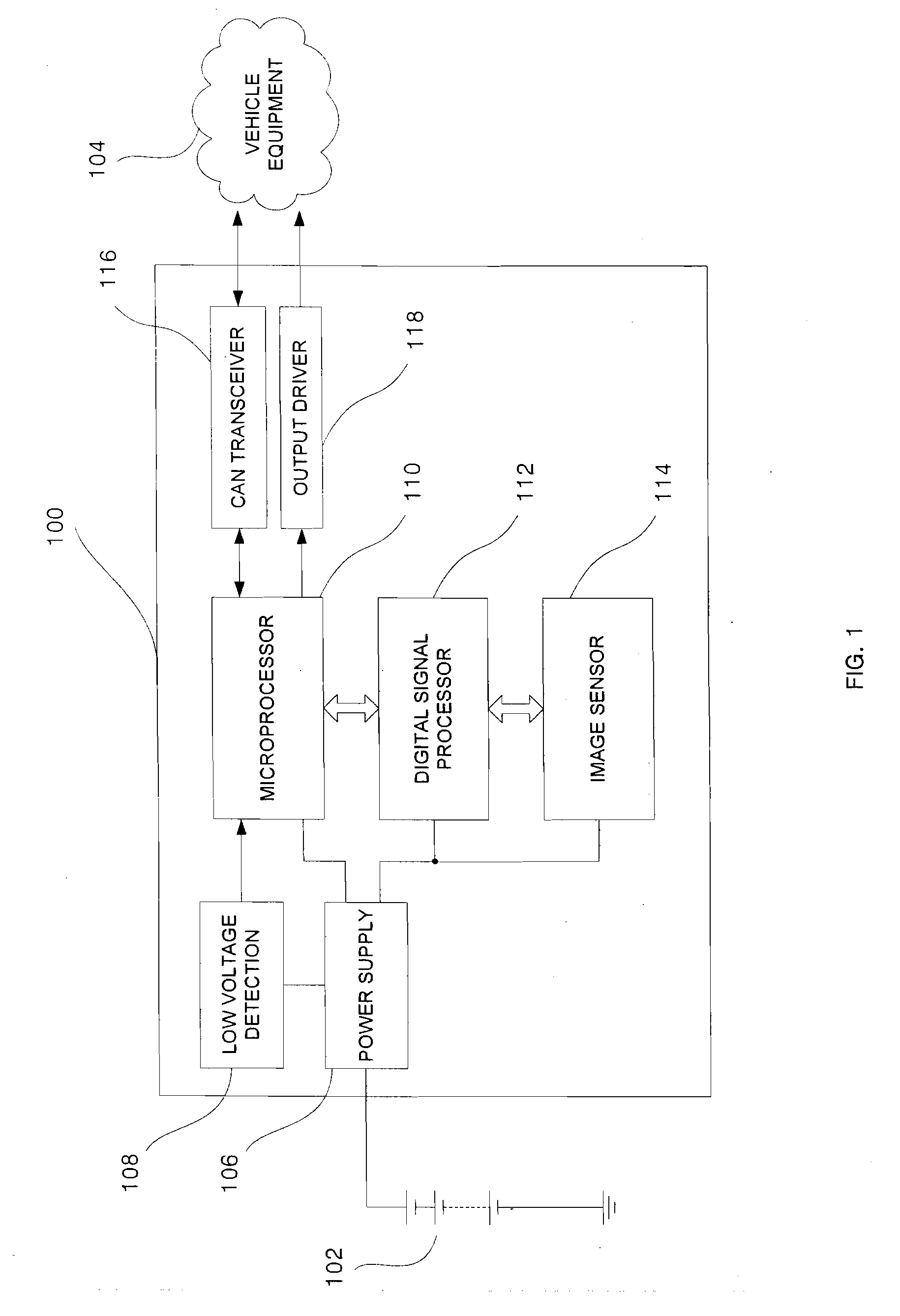
[0022]Referring to FIG. 1, a block diagram of an exemplary electronic control unit 100 in which the principles of the present invention may be advantageously practiced is illustrated generally. Electronic control unit 100 illustrates building blocks of a forward looking automotive camera. The camera may e.g. be used as part of a Lane Departure Warning System, a High Beam Control System and / or an Object Detection and classification System. Electronic control unit 100 includes an image sensor 114, which is operatively connected to digital signal processor 112. A stream of digital video is transmitted from image sensor 114 to digital signal processor 112. Image sensor control information is sent in the opposite direction from digital signal processor 112 to image sensor 114. Digital signal processor 112 analyzes the video stream provided by image sensor 114 and derives the desired vehicle feature, e.g. a decision to warn the driver of an accidental lane departure, or a decision to turn...


PUM


Abstract

In accordance with the described embodiments vehicular electronic control units and their operating methods are described which cost effectively compensate momentary external power loss by reducing the unit's power consumption while external power is lost. In an exemplary embodiment external power loss is detected by the electronic control unit's microprocessor. The microprocessor thereupon disables some components within the electronic control unit and operates with limited functionality for the duration of external power loss. The electronic control unit uses internal energy storage, e.g. a hold capacitor, to sustain its limited functionality operation. Upon recovery from the external power loss the electronic control unit resumes full operation.

Description

BACKGROUND OF THE INVENTION[0001]1. Field of the Invention[0002]The present invention generally relates to electronic control units and, and more particularly, to vehicular electronic control units with power loss compensation.[0003]2. Background of the Invention[0004]Automobiles are increasingly using electronic control units (ECUs) to control vehicle equipment based on sensor data. A forward looking camera may, for example, detect preceding and oncoming traffic and control the vehicle's headlights in response thereto. More specifically, the camera may automatically control high headlights beams to turn on only if no other vehicles will be subjected to undue glare. A camera may also detect lane markings and warn the driver in case of accidental lane departures. A radar sensor may alert the driver to objects in the driver's blind spot.[0005]The increasing sophistication of vehicle features requires calculating complex algorithms and / or processing large amounts of sensor data. Especi...

Claims


Application Information

Patent Timeline
IPC IPC(8): G06F1/28
CPCG06F1/305
Inventor GRONEMEIER, FRANKFERBER, MARKUSFRANCK, CHRISTIANEHRICH, JESKO
Owner HELLA KG HUECK & CO
Why Eureka
Eureka Blog
Learn More