Vibration absorber, method of reducing disturbing vibration, and photolithography machine

A vibration damper and vibration isolator technology, which is applied in the field of photolithography machines, can solve the problems of reducing the vibration damping effect and the vibration damper cannot be isolated, and achieve the effects of improving the vibration damping effect, reducing production costs, and improving stability

Active Publication Date: 2020-09-11
SHANGHAI MICRO ELECTRONICS EQUIP (GRP) CO LTD
View PDF4 Cites 0 Cited by
  • Summary
  • Abstract
  • Description
  • Claims
  • Application Information

AI Technical Summary

Problems solved by technology

[0005] The invention provides a method for reducing disturbing vibration, which is used to solve the problem that the air spring-based shock absorber cannot isolate self-vibration and reduce the vibration-damping effect

Method used


Image

  • Vibration absorber, method of reducing disturbing vibration, and photolithography machine
  • Vibration absorber, method of reducing disturbing vibration, and photolithography machine
  • Vibration absorber, method of reducing disturbing vibration, and photolithography machine

Examples


Embodiment 1

[0033] See figure 2 , a photolithography machine, including a base 10, a machine load 20, and a shock absorber arranged between the base 10 and the machine load 20, the shock absorber makes the base 10 and the An elastic connection is formed between the machine loads 20 to reduce the transmission of vibrations.

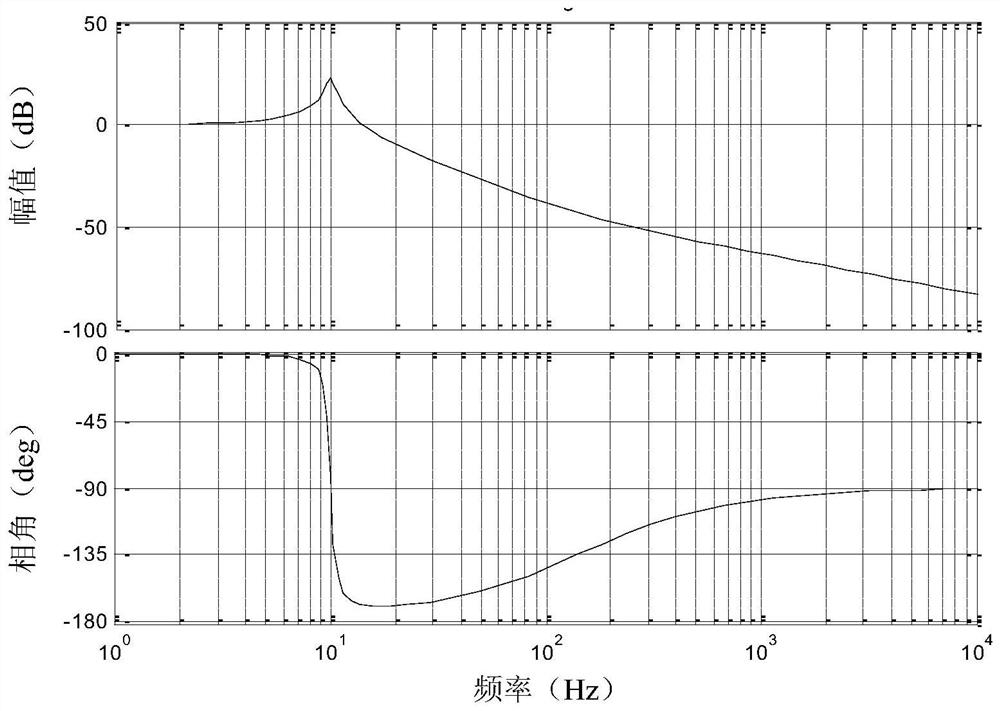
[0034] The vibration absorber includes a series connection of a vibration isolator and a damper, the vibration isolator is connected to the base 10 , and the damper is connected to the machine load 20 . In this embodiment, the vibration isolator is an air spring 31, and the vibration transmission rate formula of the air spring 31 is:

[0035]

[0036] Among them, M is the load mass, C 1 is the air spring damper, K 1 is the stiffness of the air spring, and s is a complex variable (complex field).

[0037] The vibration transmission rate curve of the air spring 31 is shown in image 3 , represented by a Bode diagram, which consists of two diagrams: one is the a...

Embodiment 2

[0052] See Image 6 The difference between the second embodiment and the first embodiment is that the vibration isolator is a steel spring 35, one end of the steel spring 35 is connected to the base 10, and the other end is connected to the damper, and the control valve is the The controller 343 adjusts the elongation of the steel spring 35 through the controller 343 . The vibration is transmitted to the shock absorber through the base 10. Firstly, the steel spring 35 performs vibration isolation on the incoming vibration. The steel spring 35 has a self-vibration phenomenon, and it is easy to transmit the intermediate frequency vibration of 6-100 Hz. The steel spring 35 has a small critical damping ratio and poor vibration isolation capability near the resonance frequency. Therefore, the rubber spring 321 is connected in series with the steel spring 35 to effectively isolate the vibration that the steel spring 35 cannot isolate. At the same time, when vibrations are generated...


PUM


Abstract

The invention discloses a method for reducing interference vibration, which includes steps of performing first isolation on interference vibration by a vibration isolator, and performing a secondary isolation on the disturbance vibration from the vibration isolator by adopting a damper. The method of reducing the interference vibration adopts two vibration reducing methods, thus the vibration reducing effect is improved. The invention further discloses an absorber, which is arranged between a substrate of the device and a machine load; the absorber can reduce the influence of the interferencevibration on the device and further eliminate the target position change of the machine load in relative the external world under the heavy load compression for a long time. The invention further discloses a photoetching machine applying the absorber. After adopting the absorber, the stability of the photoetching machine is improved.

Description

technical field [0001] The invention relates to a shock absorber, a method for reducing disturbing vibration, and a photolithography machine. Background technique [0002] Generally, equipment sensitive to vibration, such as a photolithography machine, etc., its components include a base and a machine load, the base is fixed on the ground or a platform, and the machine load is arranged on the base, so The machine loads include machine loads and vibration sensitive components, the machine loads supporting the vibration sensitive components. Taking a lithography machine as an example, the vibration-sensitive components include the workpiece table, mask table, exposure objective lens, and measuring equipment. The factors that affect the vibration of the base mainly include the introduction of foundation vibration, the relative load of internal components of the machine, and so on. The reaction force and torque generated by the outside world on the machine caused by the movemen...

Claims


Application Information

Patent Timeline
Patent Type & Authority Patents(China)
IPC IPC(8): G03F7/20
CPCG03F7/70716G03F7/709
Inventor 周宏权刘赟
Owner SHANGHAI MICRO ELECTRONICS EQUIP (GRP) CO LTD
Why Eureka
Try Eureka