Large-dynamic micro-current detection circuit

A detection circuit and micro-current technology, applied in the direction of measuring current/voltage, measuring device, measuring electrical variables, etc., can solve the problems that the lower limit of measurement is difficult to reach, difficult to continuously measure large dynamics, etc., and achieve low cost, environmental noise suppression, and process good sex effect

Active Publication Date: 2018-02-16
成都兴睿宝电子科技有限公司
View PDF10 Cites 0 Cited by
  • Summary
  • Abstract
  • Description
  • Claims
  • Application Information

AI Technical Summary

Problems solved by technology

The key difficulty limiting the application of the capacitance integration method lies in the release method of the capacitance charge
There are many ways to realize the automatic release of capacitive charge, but limited by the selection and application method of the discharge switch, the lower limit of measurement is difficult to reach 10 -12 A level, it is also difficult to achieve continuous large dynamic measurement

Method used


Image

  • Large-dynamic micro-current detection circuit
  • Large-dynamic micro-current detection circuit
  • Large-dynamic micro-current detection circuit

Examples


Embodiment 1

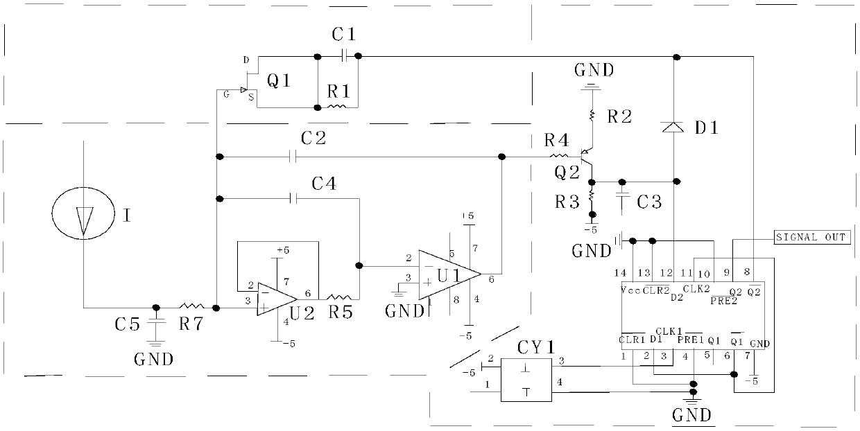
[0026] Such as Figure 1-3 As shown, the present invention includes a large dynamic micro-current detection circuit, including

[0027] Leakage discharge switch circuit: including JFET input impedance Q1, the G pole of Q1 is connected to the non-inverting input terminal of the operational amplifier U2 in the current integration circuit, the D and S poles of Q1 are short-circuited to the left end of capacitor C1 and resistor R1; capacitor C1 and The right ends of the resistor R1 are connected together, and then connected to the K pole of the diode D1 in the charge discharge and frequency generation circuit and the double D flip-flop U3 foot;

[0028] Q1 is an ultra-high input impedance JFET, connect it to a special diode, its reverse saturation current Is is 0.2pA (VGS=-20V), according to the diode equation, the forward current through the diode I=Is(e U / UT -1), U is the diode forward voltage, UT is the temperature voltage equivalent, at normal temperature (300K), UT≈26mV. ...

Embodiment 2

[0034] This embodiment is preferably as follows on the basis of Embodiment 1: the current integration circuit includes operational amplifier U1, operational amplifier U2, resistor R5, resistor R6, resistor R7, capacitor C2, capacitor C4 and capacitor C5, and the left end of resistor R6 is the current input pin, the right end of resistor R6 is connected to the left end of resistor R7; one end of capacitor C5 is connected to the connection point of resistor R6 and resistor R7, and the other end is connected to ground; the right end of resistor R7 is connected to the positive phase input end of operational amplifier U2; operational amplifier U2 The 7-pin is connected to the +5V power supply, and the 4-pin is connected to the -5V power supply; the inverting input terminal and the output terminal are shorted together, and then connected to the left end of the resistor R5; the right end of the resistor R5 is connected to the inverting input terminal of the operational amplifier U1; th...


PUM


Abstract

The invention discloses a large-dynamic micro-current detection circuit comprising a leakage discharge switch circuit, a current integral circuit, and a charge discharging and frequency generating circuit. The leakage discharge switch circuit includes a JFET input impedance Q1; a G pole of the Q1 is connected with a non-inverting input terminal of an operational amplifier U2 in the current integral circuit; D and S poles of the Q1 is are in short-circuit connection with left ends of a capacitor C1 and a resistor R1; the right ends of the capacitor C1 and the resistor R1 are connected and thenare connected to a K pole of a diode D1 and a Q2-pin of a dual-D trigger U3 in the charge discharging and frequency generating circuit. The current integral circuit consists of an input buffer circuitformed by connection of an operational amplifier U2 and a follower, an operational amplifier U1 and an integrating capacitor. A COMS dual-D trigger and a peripheral circuit are combined to form a charge absorption circuit and an output frequency generation circuit in the charge discharging and frequency generating circuit. On the basis of the principle, the lower limit of micro-current detectionreaches an order of 10<-12>A; and large-dynamic continuous measurement is realized.

Description

technical field [0001] The invention relates to the technical field of micro electric signal detection, in particular to a large dynamic micro current detection circuit. Background technique [0002] Weak current measurement technology is widely used in nuclear technology, vacuum measurement technology, biomedicine, astronomy, magnetism, geoscience, physics, electrochemistry and other related fields. In many engineering applications, micro-current measurement mainly focuses on 10 -12 A—10 -6 There are two main methods for micro-current measurement suitable for this range: resistance transconductance method and capacitance integration method. [0003] Resistance transconductance method, such as figure 2 Shown Vout=-Iin*R. Limited by amplifier current noise, thermal noise, zero drift, temperature drift, resistance thermal noise, and resistance temperature drift coefficient, when R is a certain value, it can generally meet the measurement of up to 3.5 orders of magnitude. ...

Claims


Application Information

Patent Timeline
Patent Type & Authority Applications(China)
IPC IPC(8): G01R19/252
CPCG01R19/252
Inventor 熊慧贺良武柳灵
Owner 成都兴睿宝电子科技有限公司
Why Eureka
Try Eureka