
Fiber laser self-propulsion cosmic light ship control system

A fiber laser and self-propelled technology, which is applied in the direction of aerospace vehicle propulsion system devices, aerospace equipment, aerospace equipment, etc., can solve the problem of large beam waist radius and far-field divergence angle, increased difficulty in aircraft tracking and aiming, The problem of high heat generation in the laser system achieves the effect of high beam quality, low loss, and easy system integration

Pending Publication Date: 2018-02-09
NORTH CHINA INST OF AEROSPACE ENG
View PDF6 Cites 5 Cited by
  • Summary
  • Abstract
  • Description
  • Claims
  • Application Information

AI Technical Summary

Problems solved by technology

Although the free electron laser has the advantages of adjustable wavelength, high power and efficiency, but the single pulse energy is small (J or mJ level), the average power is low, and the repetition rate is low, which cannot meet the requirements of remote laser propulsion.
[0007] TEA Pulse CO 2 The disadvantages of lasers are also quite obvious
[0008] (1)CO 2 The quality of the laser output from the laser is poor, the beam waist radius and the far-field divergence angle are large, which makes it more difficult to track and aim the aircraft. The only way to increase the laser power density in the fuel cavity is to increase the output power
[0009] (2) The electro-optical conversion efficiency is low, only about 15%, and the energy consumption is huge
[0010] (3)CO 2 The laser system generates a lot of heat and needs a corresponding cooling device. Due to the existence of thermal effects, the stability of the system is not good
[0011] (4) CO 2 Lasers are relatively bulky and can only be used on land. Therefore, it is necessary to find a laser light source that is more suitable for laser propulsion technology to replace CO2 lasers

Method used


Image

  • Fiber laser self-propulsion cosmic light ship control system

Examples


Embodiment Construction

[0021] (1) Ground-based fiber laser laser propulsion technology

[0022] ①Theoretical research and software simulation of ground-based fiber laser beam emission and control system to realize the control of high-power fiber laser power, output waveform, and output pulse frequency;

[0023] ②Design the atmospheric conduction optical path and tracking control system of the ground-based fiber laser;

[0024] ③Design the fiber guidance control system of the ground-based fiber laser;

[0025] ④Design the air-conduction air-breathing mode laser thruster of the ground-based fiber laser;

[0026] ⑤Design the fiber-guided air-breathing mode laser thruster for the ground-based fiber laser;

[0027] ⑥Design the ablation mode laser thruster of the ground-based fiber laser in the atmospheric conduction rocket;

[0028] ⑦Design ablation-mode laser propulsion for ground-based fiber lasers and fiber-guided rockets;

[0029] ⑧Theoretical calculation of parameters such as the specific impuls...


PUM


Abstract

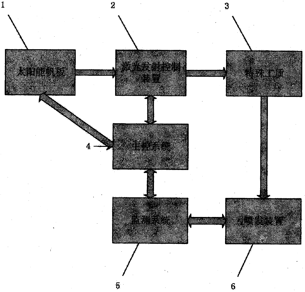
The invention relates to a fiber laser self-propulsion cosmic light ship control system, and belongs to the technical field of new concept spaceflight. The invention relates to a fiber laser self-propulsion device system and a control system. In order to solve the problem that the orbit and the flight attitude are difficult to quickly and accurately control by a conventional airship propulsion control system, the invention adopts a technique of applying the accurate controllability of a fiber laser to a control system of an airship. The fiber laser is applied to a laser propulsion device to replace a conventional chemical propulsion device; in the space, a solar sailboard is used for providing electric energy, the magnitude of the power capacity of the laser is controlled by a laser transmitting control device, in the propulsion device, the laser reacts with a special working substance, and a high-temperature high-pressure gas is generated to be sprayed out to generate power; accordingto the orbit and the attitude of the airship, fed back by a monitoring system in a real-time manner, spraying devices at different positions are selected to realize quick adjustment; the principle lies in that the magnitude of the thrust of each propulsion device is controlled through controlling the magnitude of the power capacity of the laser, so that the flight path and the flight attitude ofthe airship can be quickly and accurately controlled.

Description

technical field [0001] The invention belongs to the field of new concept aerospace technology, and the invention relates to a fiber laser self-propelling device system and a control system. Background technique [0002] The spacecraft control system is an important part of aerospace engineering. It has long working hours, high precision requirements, special environment, and is limited by conditions such as weight and energy consumption. The system structure is quite different from the control system of the launch vehicle. [0003] Spacecraft control includes attitude control and orbit control. In deep space exploration, the spacecraft needs to have high control accuracy. The initial speed and direction of the interstellar flight orbit have slight errors, and there will be large deviations when reaching the end point. For example: at the end of the initial guidance of a spacecraft landing on Mars, if the speed error is 0.3m / s and the direction error is 1′, the distance error...

Claims


Application Information

Patent Timeline
Patent Type & Authority Applications(China)
IPC IPC(8): B64G1/24B64G1/40
CPCB64G1/242B64G1/409B64G1/245
Inventor 檀朝彬侯思林张恒梁星郭畅张雪莹丘锦鸿
Owner NORTH CHINA INST OF AEROSPACE ENG
Learn More