Ceramic antenna used for mobile terminal and production technology
A ceramic antenna and mobile terminal technology, applied in the directions of antennas, antenna parts, antenna supports/installation devices, etc., can solve the problems of complex lamination process, different resonant frequencies, complex production processes, etc., and achieve small size and simplify production. Process, effect of increased risk of short circuit
- Summary
- Abstract
- Description
- Claims
- Application Information
AI Technical Summary
Problems solved by technology
Method used
Image

Examples
Embodiment 1
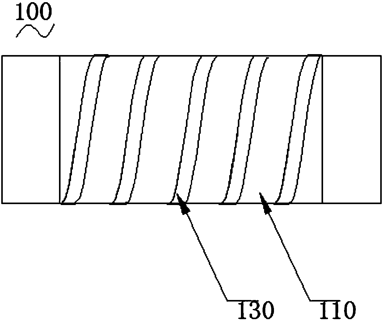
[0039] Such as figure 2 and image 3 Shown are the schematic structural diagram and the test result diagram of the ceramic antenna of the first embodiment, respectively.
[0040] A ceramic antenna 100 for a mobile terminal, comprising a ceramic rod 110, metal terminals 120 located at both ends of the ceramic rod 110, and a metal wire 130 wound on the surface of the ceramic rod 110; the length of the ceramic rod 110 is L, and the ceramic rod The diameter of 110 is D, the dielectric constant is Er, the speed of light is c, the resonant frequency of the ceramic antenna 100 is f, the number of turns of the metal wire 130 around the surface of the ceramic rod 110 is N, and N*π*D+L=2 *c / (Er*f+f).
[0041] The production process of ceramic antenna 100 of the present invention is, comprises the following steps, a, make ceramic rod 110, its diameter is D, and dielectric constant is Er, b, make two metal terminals 120, connect two metal terminals 120 respectively At both ends of the...
Embodiment 2
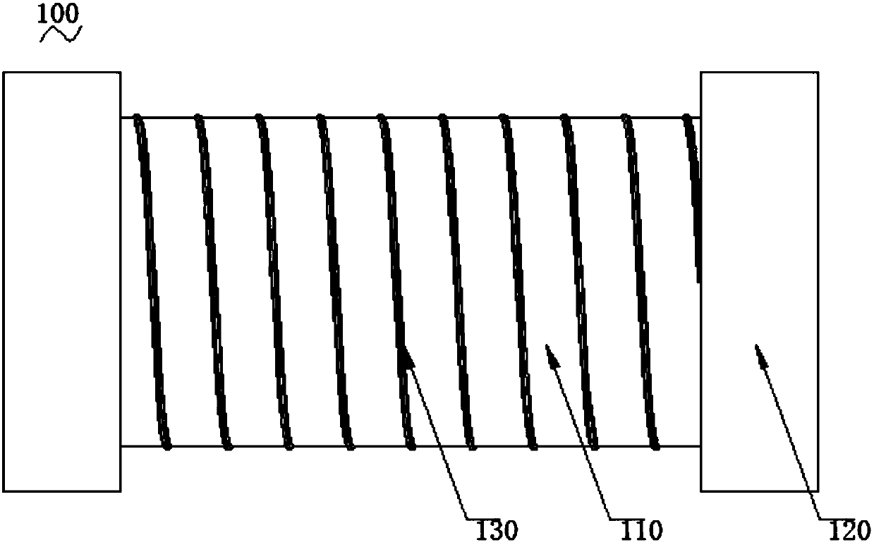
[0050] Such as Figure 4 and Figure 5 Shown are the schematic structural diagram and the test result diagram of the ceramic antenna of the second embodiment, respectively.
[0051] In this embodiment, the number of turns of the metal wire is 5, and the ceramic antenna is tested, and the test results are as follows Figure 5 . The curve in the figure reflects the voltage standing wave ratio (VSWR), and the position corresponding to the lowest point is the resonant frequency point of the ceramic antenna, indicating the frequency point where the ceramic antenna radiates the best.
[0052] Embodiment 1 and Embodiment 2 illustrate that when different resonance frequencies need to be obtained in different application occasions, it is only necessary to wind metal wires 130 with different numbers of turns on the surface of ceramic rod 110 . The production process is simple and easy to use.
Embodiment 3
[0054] Such as Figure 6 and Figure 7 Shown are the structural schematic diagram and the test result figure of embodiment three respectively.
[0055] In this embodiment, the surface of the ceramic rod 110 is integrally plated with a layer of silver, and then according to the required frequency, a pattern of 5 circles of metal wires 130 is cut on the ceramic rod 110 . The metal wire 130 is directly cut from the surface of the ceramic rod 110 electroplated with a silver-plated layer, no winding is required, the subsequent debugging is convenient, the processing difficulty is further reduced, and the production process is simple.
PUM
| Property | Measurement | Unit |
|---|---|---|
| Length | aaaaa | aaaaa |
| Diameter | aaaaa | aaaaa |
Abstract
Description
Claims
Application Information
 - R&D
- Intellectual Property
- Life Sciences
- Materials
- Tech Scout
- Unparalleled Data Quality
- Higher Quality Content
- 60% Fewer Hallucinations
Browse by: Latest US Patents, China's latest patents, Technical Efficacy Thesaurus, Application Domain, Technology Topic, Popular Technical Reports.
© 2025 PatSnap. All rights reserved.Legal|Privacy policy|Modern Slavery Act Transparency Statement|Sitemap|About US| Contact US: help@patsnap.com