
Valve cam provided with cosine-constant speed type buffer section and used for internal combustion machine and lift curve determination method of valve cam

A valve cam and constant velocity curve technology, applied in valve details, valve drive devices, etc., can solve the problems of high movement speed and poor stability at the connection of the working section, and achieve the effect of reducing impact

Active Publication Date: 2018-01-26
哈尔滨船科动维消声技术有限公司
View PDF3 Cites 3 Cited by
  • Summary
  • Abstract
  • Description
  • Claims
  • Application Information

AI Technical Summary

Problems solved by technology

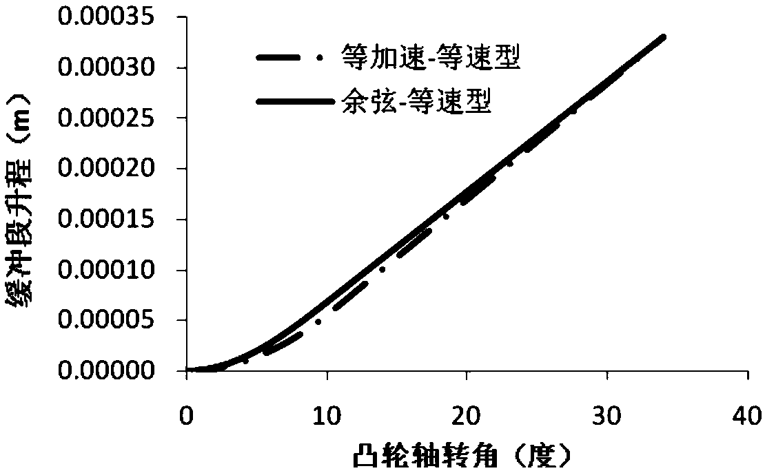
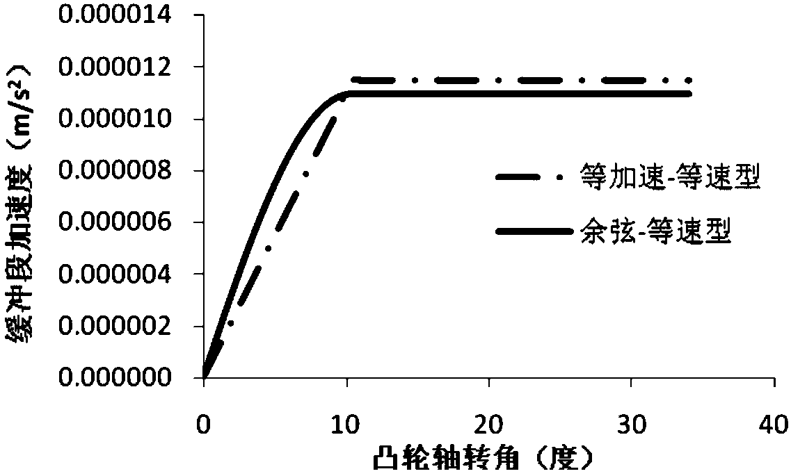
When the lift and wrap angle of the buffer section are the same, the velocity, acceleration and jerk curves of the cosine buffer section are smoother. At the end of the buffer section, the second derivative of the lift function is zero, but its third derivative is not zero, so the stability of the connection with the working section is slightly poor, and the movement speed is relatively high when the air valve is opened; the high-order derivatives of the lift curve at the end of the buffer section of the constant-acceleration-constant velocity type are all zero, which can ensure the same working The stability of the end connection, and has the advantages of constant opening and seating of the air valve, but there will be a greater impact at the subsections of the constant acceleration section and the constant velocity section

Method used


Image

  • Valve cam provided with cosine-constant speed type buffer section and used for internal combustion machine and lift curve determination method of valve cam
  • Valve cam provided with cosine-constant speed type buffer section and used for internal combustion machine and lift curve determination method of valve cam
  • Valve cam provided with cosine-constant speed type buffer section and used for internal combustion machine and lift curve determination method of valve cam

Examples


Embodiment Construction

[0041] The present invention is described in more detail below in conjunction with accompanying drawing example:

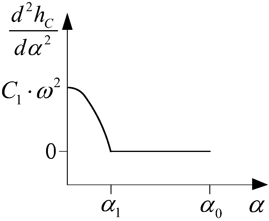
[0042] combine Figure 1-5 , the lift curve h of the cosine-constant velocity type buffer section of the present invention C (α) consists of two sections, and its expression can be written as:

[0043]

[0044] The corresponding speed, acceleration and jerk curve expressions are:

[0045]

[0046]

[0047]

[0048] In the formula, α 1 is the wrapping angle of the cosine segment, α 0 is the wrapping angle of the buffer section, α 1 、C 1 ,E 0 ,E 1 are undetermined constants,

[0049] The size can be determined by the boundary conditions and α=α 1 The continuity condition is obtained. Specifically follow the steps below:

[0050] Step 1: Given the lift h of the buffer section 0 , buffer section wrap angle α 0 And cosine section wrap angle factor G.

[0051] Step 2: Determine the wrap angle of the cosine segment according to the wrap angle co...


PUM


Abstract

The invention aims to provide a valve cam provided with a cosine-constant speed type buffer section and used for an internal combustion machine and a lift curve determination method of the valve cam.The cosine-constant speed type buffer section is composed of two segments, namely the acceleration curve of the first segment is a cosine curve, and the acceleration curve of the second segment is a constant-speed curve; the expression of the lift curve of the valve cam used for the internal combustion machine is that when 0<=alpha<=alpha1, hC(alpha)=C1(1-cosomega alpha); when alpha1<=alpha<=alpha0, hC(alpha)=E0+E1alpha; and the undetermined constants C1, E0 and E1 of the cosine-constant speed type buffer section are worked out according to the boundary conditions and the continuity conditionat the position where alpha=alpha1, namely C1=h0 / [1+cos(omegaG alpha0)+omega alpha0(1-G)sin(omegaG alpha0)], E1=C1.omega.sin(omegaG alpha0), and E0=h0 / alpha0 E1. According to the valve cam provided with the cosine-constant speed type buffer section and used for the internal combustion machine and the lift curve determination method of the valve cam, the third derivative of the tail end of the buffer section can be kept zero, the discontinuity of the segments of the buffer section can be avoided, and thus impact, vibration and noise, caused by the cam profile, of a valve mechanism can be reduced easily.

Description

technical field [0001] The invention relates to a gas distribution mechanism of an internal combustion engine, specifically a gas distribution cam. Background technique [0002] The valve train is one of the main moving mechanisms of the internal combustion engine. The gas distribution mechanism is composed of multiple parts connected to each other. During the operation of the diesel engine, due to changes in force and heat, it will expand and contract to varying degrees. In order to ensure that the valve face and the valve seat can be tightly closed when the valve is closed, there must be a gap in the entire transmission chain of the valve mechanism. Due to the existence of the air valve gap, the movement of the tappet and the air valve cannot be synchronized. At the same time, generally in order to obtain a sufficiently large cross section of the air valve, the tappet often starts to move with a relatively large acceleration. In this way, when the tappet overcomes the ga...

Claims


Application Information

Patent Timeline
Patent Type & Authority Applications(China)
IPC IPC(8): F01L1/08
Inventor 国杰张文平张新玉程艳萍
Owner 哈尔滨船科动维消声技术有限公司
Learn More