
Novel winder for dust collector

A technology of wire reels and vacuum cleaners, which is applied to the installation of cables, the arrangement of cables between relative moving parts, and electrical components, etc. It can solve the problems of affecting the braking control effect, practical limitations, poor compatibility of vacuum cleaners, etc., and achieves a wide range of applications. Market application prospects, increased location selection space, and the effect of strong compatibility

Inactive Publication Date: 2010-09-29
LG ELECTRONICS (TIANJIN) APPLIANCES CO LTD
View PDF0 Cites 10 Cited by
  • Summary
  • Abstract
  • Description
  • Claims
  • Application Information

AI Technical Summary

Problems solved by technology

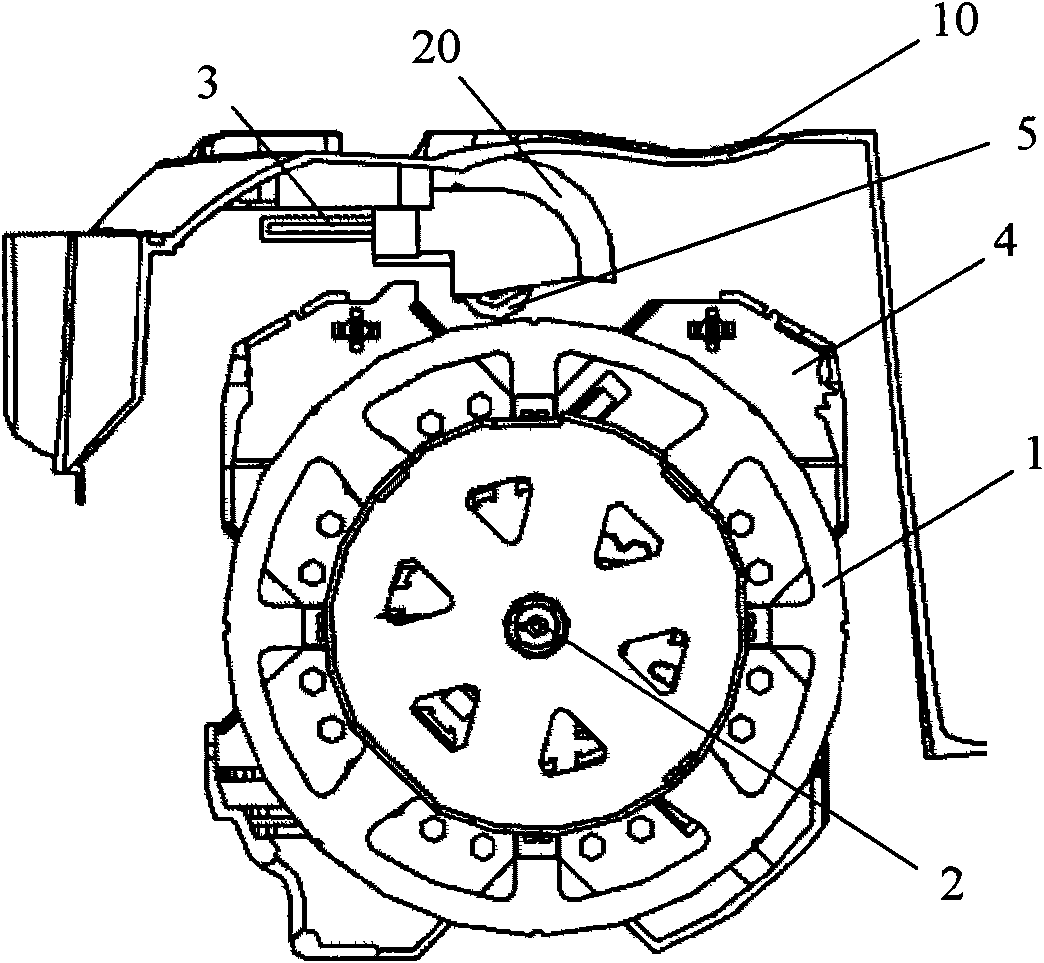
[0011] However, for the vacuum cleaner cord reel in the prior art, in order to make the brake button 3 of the cord reel better engage with the groove on the outer periphery of the cord reel 1, so as to effectively control the rotation of the cord reel 1, The position of the brake button 3 of the cord reel is relatively high, and it must be set in front of the reel 1. Therefore, it is practical for vacuum cleaner models that require the brake button 3 of the cord reel to be located at the rear due to appearance reasons. The performance is limited, so that the existing structure of the vacuum cleaner cord reel has poor compatibility with the vacuum cleaner
[0012] In addition, since the left and right sides of the braking positioning wheel 5 are not limited, the stability of the braking positioning wheel 5 is not good, which seriously affects the braking control effect of the braking positioning wheel 5 on the reel disc 1, resulting in The power cord does not rotate smoothly

Method used


Image

  • Novel winder for dust collector
  • Novel winder for dust collector
  • Novel winder for dust collector

Examples


Embodiment Construction

[0026] In order to enable those skilled in the art to better understand the solution of the present invention, the present invention will be further described in detail below in conjunction with the accompanying drawings and embodiments.

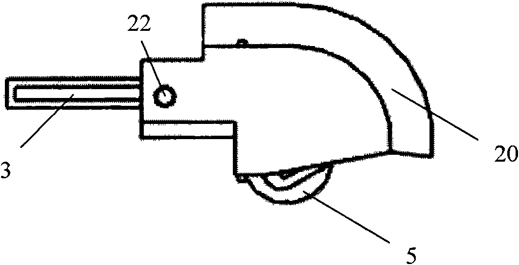
[0027] figure 2 It is a structural schematic diagram of a novel cord reel for a vacuum cleaner provided by the present invention, image 3 It is an enlarged schematic diagram of the front of the connecting part of the brake button of the cord reel, the action bracket of the cord reel, and the brake positioning wheel 5 in the novel cord reel of a vacuum cleaner provided by the present invention, Figure 4 for image 3 An enlarged cross-sectional schematic diagram of the connecting part of the braking button of the cord reel, the action bracket of the cord reel, and the brake positioning wheel 5 .

[0028] see Figure 2 to Figure 4 , the present invention provides a novel cord reel for a vacuum cleaner, the vacuum cleaner includes a vacuum...


PUM


Abstract

The invention discloses a novel winder for a dust collector. The dust collector comprises an upper dust collector cover (10), wherein the winder comprises a winding wheel disk (1); the upper dust collector cover (10) is fixedly provided with a winder actuating bracket (20); an actuating arm (21) is arranged in the winder actuating bracket (20); one end of the actuating arm (21) is rotatably provided with a brake positioning wheel (5); the brake positioning wheel (5) is engaged with a notch at the periphery of the winding wheel disk (1); the other end of the actuating arm (21) is fixedly connected with a winder brake key (3); and one end of the winder brake key (3) adjacent to the actuating arm (21) is hinged with the winder actuating bracket (20). By increasing the position selection space for the winder brake key, the winder is suitable for various types of dust collectors, has high compatibility, can also increase the stability of the power line loop and has simple structure and great significance in production practice.

Description

technical field [0001] The invention relates to the technical field of mechanical dust removal, in particular to a novel cord reel for a vacuum cleaner. Background technique [0002] Generally, a vacuum cleaner is a device that uses a vacuum to generate suction to inhale air, make the air flow through various filters, filter foreign objects in the air, and clean the room. [0003] Generally speaking, a vacuum cleaner mainly includes a suction device and a suction pipeline. The suction device mainly formed by a motor and a fan is arranged in the body. The suction pipeline includes a suction head and a suction pipe. The suction head has a downward opening. The suction port communicates with the air inlet of the fan inside the body through the telescopic pipe and the flexible pipe of the suction pipe. When the vacuum cleaner is running, the motor drives the impeller of the fan to rotate at a high speed, exhausting the air in the vacuum cleaner, forming an instantaneous vacuum ...

Claims


Application Information

Patent Timeline
Patent Type & Authority Applications(China)
IPC IPC(8): A47L9/26
Inventor 乔亮
Owner LG ELECTRONICS (TIANJIN) APPLIANCES CO LTD
Learn More