Closed rotary control system and crane

A control system and crane technology, applied in cranes, fluid pressure actuation system components, mechanical equipment, etc., can solve the problems of rapid oil temperature rise, large amount of calculation, poor stability, etc.

Active Publication Date: 2019-10-01
JIANGSU XCMG CONSTR MASCH RES INST LTD
View PDF6 Cites 10 Cited by
  • Summary
  • Abstract
  • Description
  • Claims
  • Application Information

AI Technical Summary

Problems solved by technology

[0007] (1) For a closed system, if the relief valve is used for buffering, it is easy to cause the oil temperature to rise rapidly and reduce the system efficiency;
[0008] (2) Free sliding is achieved by means of on-off valves or speed regulating valves, without considering the speed process limitations of different working conditions (such as different outrigger lengths), and the free sliding process is easy to shake;
[0009] (3) Limiting the maximum rotation speed only according to the current working conditions cannot solve the vibration problem during the acceleration and deceleration of the rotation; at the same time, only limiting the maximum speed according to the working conditions will cause the control range of the handle to decrease, and the angle of the second half of the handle will appear If the speed changes but the speed remains the same, the user experience is poor; or the compensation control interval is mapped from the original control interval, and the calculation amount is large;
[0010] (4) The slewing speed is controlled based on the slewing acceleration, the rate of change of the slewing speed or the rate of change of the engine speed, without compensation from the operator's control process, because of the inertia of different loads, the stability control is performed when the jitter has already occurred, and the stability is poor;
[0011] (5) It does not consider the stable control and response of the slewing under different load conditions (such as heavy load start-up or high-speed slewing speed reduction)
[0012] (6) When the rotary handle returns to the position, the variable pump displacement swing angle is not monitored. If the handle has been returned, but the pump displacement swing angle does not return to the zero range, it may easily cause safety problems

Method used


Image

  • Closed rotary control system and crane
  • Closed rotary control system and crane
  • Closed rotary control system and crane

Examples


Embodiment 1

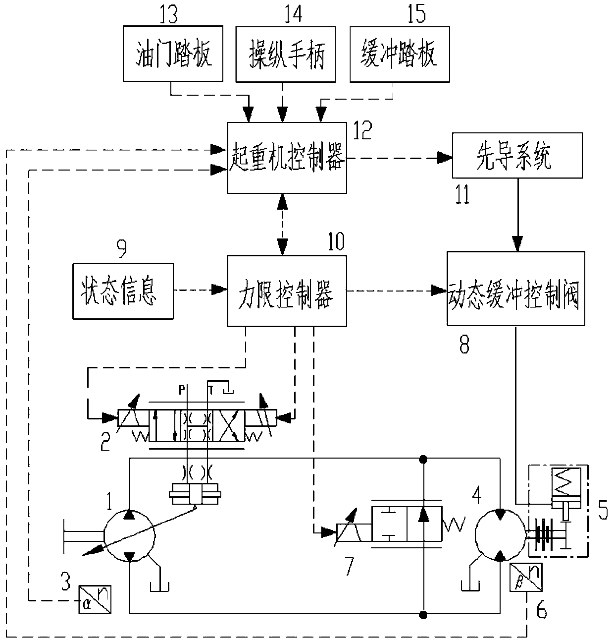
[0065] In some embodiments, such as figure 1 As shown, a closed rotary control system includes: an electronically controlled variable pump 1, a pump displacement swing angle control valve 2, a pump displacement swing angle sensor 3, a swing motor 4, a swing speed sensor 6, a state information module 9, Accelerator pedal 13, joystick 14, buffer pedal 15, dynamic brake 5, dynamic buffer control valve 8, pilot system 11, force limit controller 10, free slip control valve 7, crane controller 12;

[0066] The accelerator pedal 13, joystick 14, buffer pedal 15, pump displacement swing angle sensor 3, and slewing speed sensor 6 are respectively connected to the signal input end of the crane controller 12, and the signal output end of the crane controller 12 is connected to the pilot system 11;

[0067] The state information module 9 of the crane is connected to the signal input end of the force limit controller 10, and the signal output end of the force limit controller 10 is respect...

Embodiment 2

[0072] A closed slewing control method, comprising:

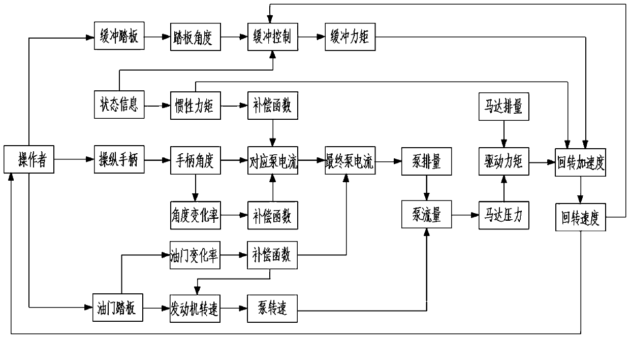
[0073] Such as figure 1 and figure 2As shown, when the operator manipulates the handle to rotate, the force limit controller 10 obtains the current state information of the crane, determines the working condition parameters such as the hoisting weight, luffing angle, and outrigger length, and transmits them to the crane controller , the crane controller obtains the corresponding handle angle change rate preset value according to the current working condition parameters. For example, the handle angle change rate preset value is 0.01° / ms when a certain working condition parameter The handle angle change information is calculated to obtain the actual change rate of the current handle angle. If the actual change rate of the current handle angle exceeds 0.01° / ms, the force limit controller 10 controls the change process of the current input to the pump displacement swing angle control valve 2. Compensation control, so that th...


PUM


Abstract

The invention discloses a closed rotary control system and a crane. Stable starting and stopping of the rotary system are achieved through a dynamic buffer control valve and a dynamic brake. Accordingto the percentage of the loading moment, the rotary maximum speed is controlled, meanwhile, the rotary speed still linearly changes in the later stroke of a control handle, and controllability in thespeed limiting speed is improved. The current of a pump displacement swing angel control valve is compensated according to the handle angle change rate, the engine rotating speed or the current of the pump displacement swing angel control valve is compensated according to the change rate of an accelerator pedal, and the control process is stably controlled. Free sliding and rotating speed compensation is carried out on the length of a telescopic arm, and stable control of free sliding and rotating is achieved. The heavy load and high speed work conditions compensate the change response process of the rotary speed, and stable speed changing is achieved. The pump displacement swing angle is monitored, safety control is achieved, and the situation that after the handle returns, the pump displacement swing angle does not return to zero, the dynamic brake is damaged, or the system is in a high-pressure overflow state is avoided.

Description

technical field [0001] The invention belongs to the technical field of construction machinery, in particular to a closed rotary control system and a crane. Background technique [0002] The main functions of the crane mainly include hoisting, telescopic, luffing and slewing, and hoisting and slewing are the two most frequently used actions of the crane in practice. Due to the large inertia of the crane, especially when the heavy-duty slewing starts and stops, it is easy to cause impact problems. Therefore, the slewing action not only affects the stability of the crane, but also has a great impact on the safety of the crane. Users usually require the slewing speed to match the current load situation, good micro-movement, smooth slewing acceleration and deceleration, and no impact during free sliding. Therefore, it is necessary Appropriate control loops and appropriate control strategies are used to achieve stable control of the slewing process. [0003] At present, the crane...

Claims


Application Information

Patent Timeline
Patent Type & Authority Applications(China)
IPC IPC(8): B66C23/86B66C13/18F15B11/08F15B11/04F15B21/08
CPCB66C13/18B66C23/86F15B11/04F15B11/08F15B21/087
Inventor 张笑周彬李波
Owner JIANGSU XCMG CONSTR MASCH RES INST LTD
Why Eureka
Try Eureka