Defoaming device

A technology of defoaming device and spraying device, which is applied in the direction of biochemical cleaning device, enzymology/microbiology device, biochemical instrument, etc., which can solve the problem of untimely extrusion defoaming and defoaming, microbial damage of fermentation, and unsatisfactory effect and other problems, to achieve the effect of wide application range and no high-energy impact

Pending Publication Date: 2018-01-09
苏州富园生物科技有限公司
View PDF6 Cites 2 Cited by
  • Summary
  • Abstract
  • Description
  • Claims
  • Application Information

AI Technical Summary

Problems solved by technology

Among them, the defoaming agent will affect the quality of the fermentation liquid. Some food fermentations are not suitable for using defoaming agents; the defoaming of the stirring paddle consumes energy and the effect is not ideal, and will form local dead ends; the sound and light energy defoaming consumes a lot of energy and has a chance The fermented microorganisms cause damage; heating and defoaming consumes energy and will affect the temperature adjustment in the reactor, and if the temperature is too high, it will cause damage to the fermenting microorganisms; extrusion defoaming and defoaming is not timely, and there will always be a lot of foam residual

Method used


Image

  • Defoaming device
  • Defoaming device

Examples


Embodiment 1

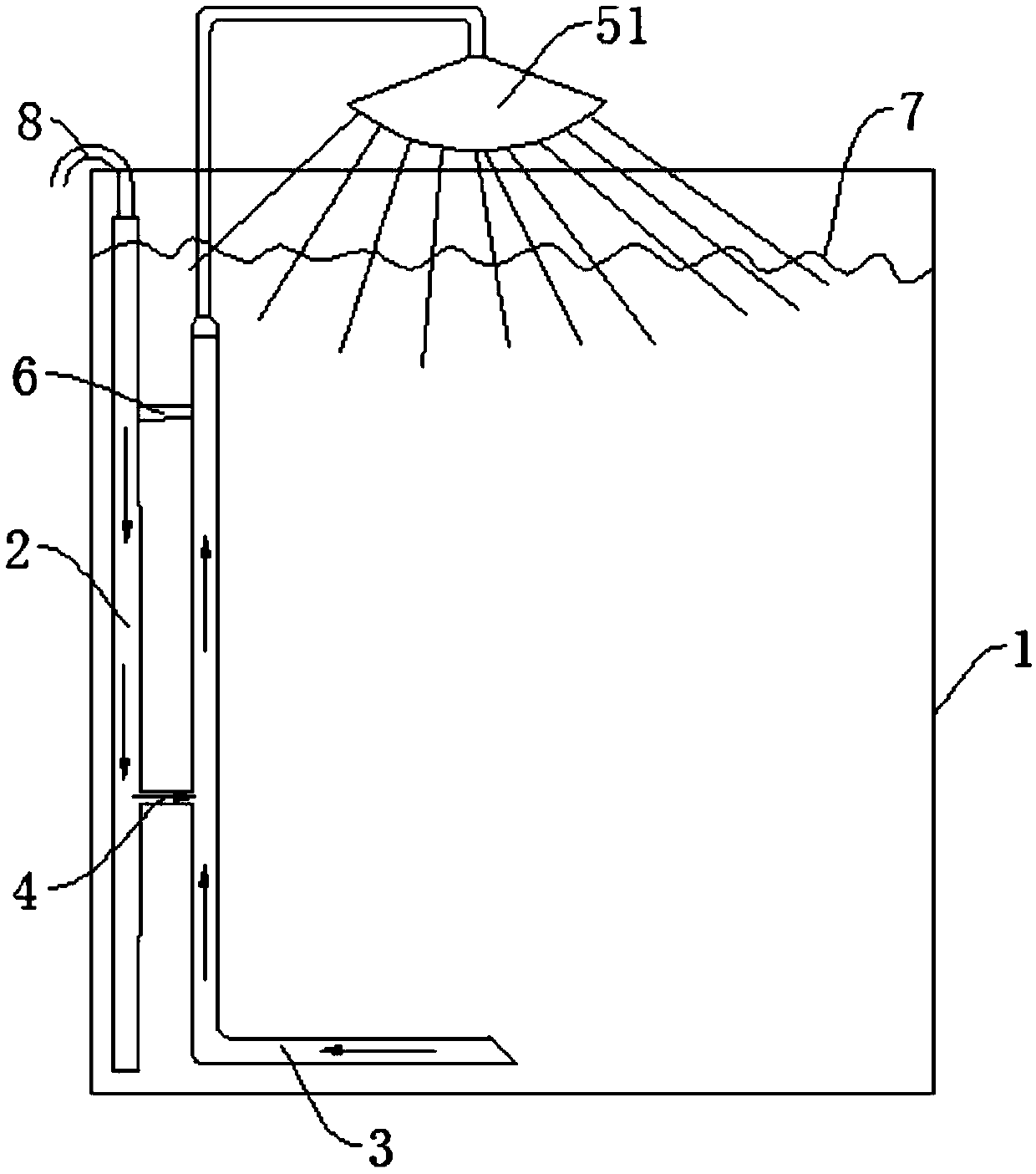
[0026] Referring to the accompanying drawings, in one embodiment of the present invention: a defoaming device, comprising: a reactor body 1, an air inlet pipe 2, a spray pipe 3 and a vent pipe 4; the air inlet pipe 2 is fixedly connected by means of a quick joint or the like On the inner wall of the reactor body 1, one end of the inlet pipe 2 is connected to an air compressor through a hose 8, and the use of compressed air to lift the liquid has more impact and can effectively ensure the defoaming effect. One end of the spray pipe 3 is arranged on the liquid surface 7 in the reactor body 1, the other end of the spray pipe 3 is arranged under the liquid surface 7 in the reactor body 1, and is arranged under the liquid surface 7 in the reactor body 1. One end of the spray pipe 3 is arranged in a trumpet shape, and the height of the liquid level 7 in the spray pipe 3 is consistent with the height of the liquid level 7 in the reactor body 1 under the action of the atmosphere. One ...

Embodiment 2

[0028] Referring to the accompanying drawings, in another embodiment of the present invention: the rest is the same as the first embodiment, the difference is that the shower device is a shower head 51, and the shower head 51 can be a common universal shower head 51. The beneficial effect of adopting the above technical solution is: the foam is broken by the liquid sprayed from the spray head 51 , the action area is large, and the efficiency is high.

Embodiment 3

[0030] Referring to the accompanying drawings, in another embodiment of the present invention: the rest are the same as in Embodiment 2, the difference is that the shower device is an arc tube 52, and the arc tube 52 communicates with the spray tube, and the arc tube 52 Close to the inner wall of the reactor body. The lower half of the arc-shaped tube 52 is provided with several fine spray holes. When the liquid enters the arc-shaped tube 52, the liquid sprays out from the spray holes to crush the foam in all directions. The beneficial effect of adopting the above technical solution is: the arc tube 52 is close to the inner wall of the reactor body, preventing the reaction liquid in the reactor body from splashing on the inner wall of the reactor, and the reactants will adhere to the inner wall of the reactor, affecting the reaction effect .


PUM

PropertyMeasurementUnit
diameteraaaaaaaaaa

Abstract

The invention discloses a defoaming device. The defoaming device comprises a reactor body, an air inlet pipe, a sprinkling pipe and a ventilating pipe, wherein the air inlet pipe is connected to the inner wall of the reactor body; one end of the air inlet pipe is connected with an air compressor through a hose; one end of the sprinkling pipe is arranged on the liquid level in the reactor body, andthe other end of the sprinkling pipe is arranged under the liquid level in the reactor body; a sprinkling device is arranged on one end of the sprinkling pipe arranged on the liquid level in the reactor body; the sprinkling device is arranged on the liquid level in the reactor body; the sprinkling pipe is communicated with the air inlet pipe through the ventilating pipe; through holes are formedin a position, which is connected with the air inlet pipe, of the sprinkling pipe; the ventilating pipe is arranged under the liquid level in the reactor body. Through the way, defoaming is carried out by adopting an air-water combination sprinkling mode, the purpose of defoaming is achieved by utilizing an impact force to break foams, defoaming dead angles can be removed, and a defoaming effect is increased; liquid in a reactor can be repeatedly utilized, no pollutant is introduced in, fermented microorganisms can be protected, and the application range is wider.

Description

technical field [0001] The invention relates to the technical field of defoaming devices, in particular to a defoaming device. Background technique [0002] During the biological reaction process, whether it is mechanical stirring, magnetic stirring, or airlift stirring, there will be foam accumulation on the surface of the reaction liquid, and the foam on the surface of the reaction liquid will affect the effect of fermentation or cultivation. As the cultivation time prolongs and the concentration of algal water becomes higher and higher, the accumulation of foam will intensify. At the same time, the foam will also become larger and affect the stirring effect, and will take part of the algae away from the algae water, affecting the reproduction speed of the algae. [0003] At present, the conventional defoaming methods include defoaming agent defoaming, stirring paddle defoaming, ultrasonic and laser defoaming, heating defoaming, extrusion defoaming and so on. Among them, ...

Claims


Application Information

Patent Timeline
Patent Type & Authority Applications(China)
IPC IPC(8): C12M1/00C12M1/21C12M1/04
Inventor 刘贯融郑旭哲
Owner 苏州富园生物科技有限公司
Why Eureka
Try Eureka