Bolt heat treatment system and method

A technology of heat treatment system and heat treatment zone, applied in heat treatment furnaces, heat treatment equipment, furnaces, etc., can solve the problems that cannot be fixed and placed according to the rules, uneven bolt tempering treatment, high production cost, etc., and achieve the effect of tempering treatment Good, uniform tempering treatment, and the effect of improving the quality pass rate

Inactive Publication Date: 2017-12-22
JIANGSU YONGHAO HIGH STRENGTH BOLT
View PDF6 Cites 6 Cited by
  • Summary
  • Abstract
  • Description
  • Claims
  • Application Information

AI Technical Summary

Problems solved by technology

[0003] Quenching and tempering treatment, it is generally customary to combine quenching and high temperature tempering heat treatment as quenching and tempering treatment, quenching and tempering treatment is widely used in various important structural parts, especially those connecting rods, bolts, Gears and shafts, etc., after quenching and tempering treatment, the tempered sorbite structure is obtained. Its mechanical properties are better than the normalized sorbite structure with the same hardness. Its hardness depends on the high temperature tempering temperature and the tempering temperature of the steel. The fire stability is related to the cross-sectional size of the workpiece, generally between HB200-350, but at present, in the process of quenching and tempering the bolts, in the tempering step, some low-temperature tempering, medium-temperature tempering or high-temperature tempering are usually used. Tempering and other treatments, due to the small size of the bolts, cannot be fixed and placed regularly when tempering a large number of bolts, resulting in uneven tempering of the bolts, poor tempering effect, and poor quality pass rate of the bolts , the efficiency of manufacturing bolts is low, and the production cost of enterprises remains high

Method used


Image

  • Bolt heat treatment system and method
  • Bolt heat treatment system and method
  • Bolt heat treatment system and method

Examples


Embodiment Construction

[0028] The present invention will be described in detail below in conjunction with the accompanying drawings and embodiments.

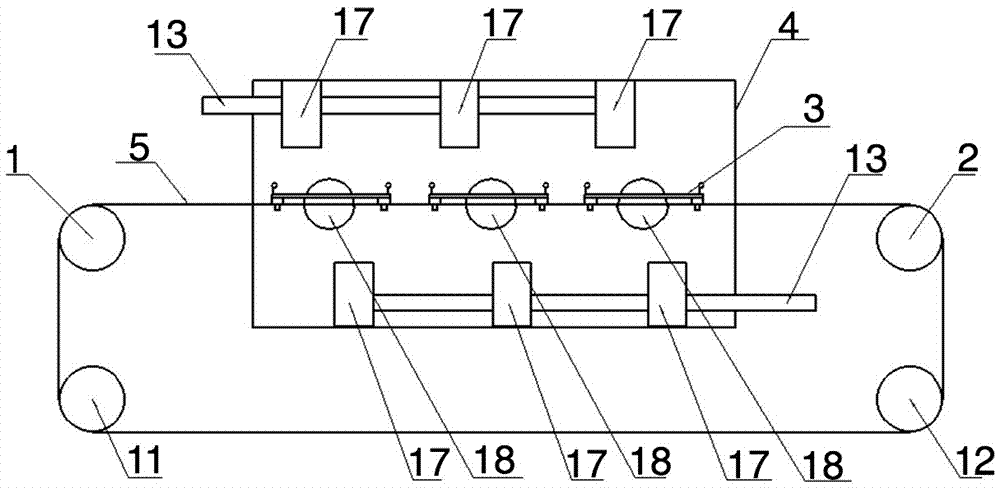
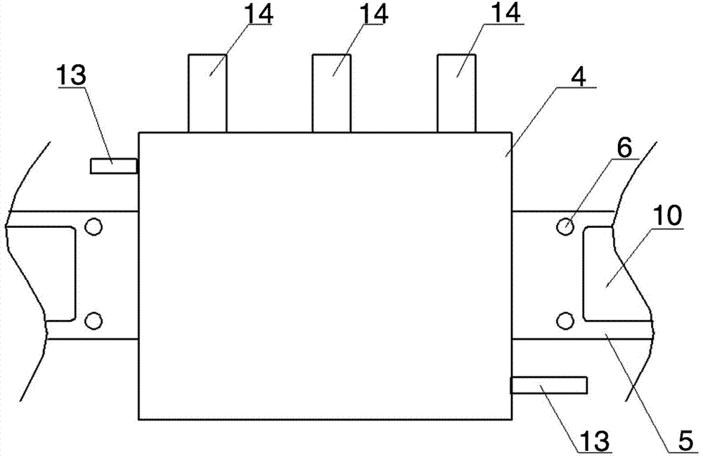
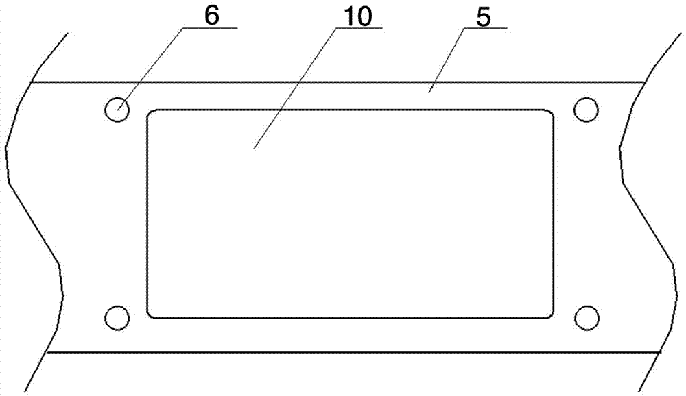
[0029] Such as Figure 1-5As shown: this embodiment is a heat treatment system for bolts, including a circulating conveying device, a bolt placement plate 3 and a heat treatment box 4, and the circulating conveying device includes a first driving roller 1, a second driving roller 2, and a conveyor belt 5, and the conveyor belt 5 The ring is looped on the first driving roller 1 and the second driving roller 2, and the conveyor belt 5 is driven by the first driving roller 1 and the second driving roller 2 to move circularly. Several heat treatment zones are formed on the conveyor belt 5. The conveyor belt 5 in the first heat treatment zone is provided with an insertion hole 6 for inserting the bolt placement plate 3, and the bottom of the bolt placement plate 3 is formed with an insertion column 7 corresponding to the insertion hole 6 on the conveyor be...


PUM


Abstract

The invention discloses a bolt heat treatment system. The bolt heat treatment system comprises a circulating conveying device, bolt carrying plates and a heat treatment box. The circulating conveying device comprises a first driving roll, a second driving roll and a conveyor belt. The conveyor belt is driven to move cyclically through the first driving roll and the second driving roll. The bolt carrying plates are inserted in the conveyor belt. A plurality of limiting holes for containing bolts are formed in each bolt carrying plate. The conveyor belt carrying the bolt carrying plates passes through the interior of the heat treatment box. The inner sidewall of the heat treatment box is provided with a high-temperature heating device. The heat treatment box is further internally provided with an air inlet pipeline and a return air pipeline communicating with an external heat supply blowing device. Meanwhile, the invention discloses a bolt heat treatment method. By means of the heat treatment method, a large number of bolts are subjected to low-temperature tempering treatment; the tempering treatment of the bolts is uniform; the tempering treatment effect is good; the quality qualified rate of the bolts is improved; the production and manufacturing efficiency of the bolts is further improved; and the production cost of an enterprise is effectively lowered.

Description

technical field [0001] The invention relates to a heat treatment system, in particular to a bolt heat treatment system and method, and belongs to the technical field of bolt production. Background technique [0002] A bolt is a mechanical part, a cylindrical threaded fastener with a nut, a type of fastener consisting of a head and a screw. The screw is a cylinder with external threads and needs to be matched with a nut. , used to fasten two parts with through holes. This connection form is called bolt connection. If the nut is unscrewed from the bolt, the two parts can be separated, so the bolt connection is a detachable connection; Heat treatment refers to a metal thermal processing process in which materials are heated, kept warm and cooled in a solid state to obtain the desired structure and properties. Metal heat treatment is one of the important processes in mechanical manufacturing. Compared with other processing technologies, heat treatment Generally, the shape and o...

Claims


Application Information

Patent Timeline
IPC IPC(8): C21D9/00C21D1/25
CPCC21D9/0093C21D1/25
Inventor 朱汉华
Owner JIANGSU YONGHAO HIGH STRENGTH BOLT
Why Eureka
Try Eureka