
Temperature compensation surface acoustic wave resonator and preparation method thereof

A surface acoustic wave, temperature compensation technology, applied in electrical components, impedance networks, etc., can solve the problems of difficult process conditions, extremely high control requirements for silicon dioxide material and thickness, and reduce the possibility of brittleness, The effect of improving stability and reliability, and improving performance

Pending Publication Date: 2017-12-19
HANGZHOU SAPPLAND MICROELECTRONICS TECH CO LTD
View PDF4 Cites 9 Cited by
  • Summary
  • Abstract
  • Description
  • Claims
  • Application Information

AI Technical Summary

Problems solved by technology

Although this method has been commercialized, it still has its limitations. For example, the material and thickness of silicon dioxide are extremely demanding, and the general process conditions are difficult to achieve.

Method used


Image

  • Temperature compensation surface acoustic wave resonator and preparation method thereof
  • Temperature compensation surface acoustic wave resonator and preparation method thereof
  • Temperature compensation surface acoustic wave resonator and preparation method thereof

Examples


Embodiment 1

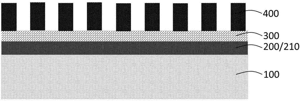
[0028] figure 1 It is a schematic cross-sectional structure diagram of the temperature-compensated surface acoustic wave resonator of the present invention. like figure 1 As shown, the temperature-compensated surface acoustic wave resonator includes a substrate 100, which is used as a supporting substrate, such as a silicon wafer, sapphire, etc.; a first adhesive film layer 200 disposed on the substrate 100; A piezoelectric material substrate 300 is arranged above 100. The piezoelectric material substrate 300 is, for example, lithium niobate, lithium tantalate, aluminum nitride, zinc oxide, etc., and the surface of the piezoelectric material substrate 300 opposite to the substrate 100 is provided with a The second adhesive film layer 210 includes an interdigitated structure above the piezoelectric material substrate 300, and the material of the interdigitated structure is, for example, aluminum, titanium, copper, chromium, silver, etc. or a combination thereof.

[0029] Spec...

Embodiment 2

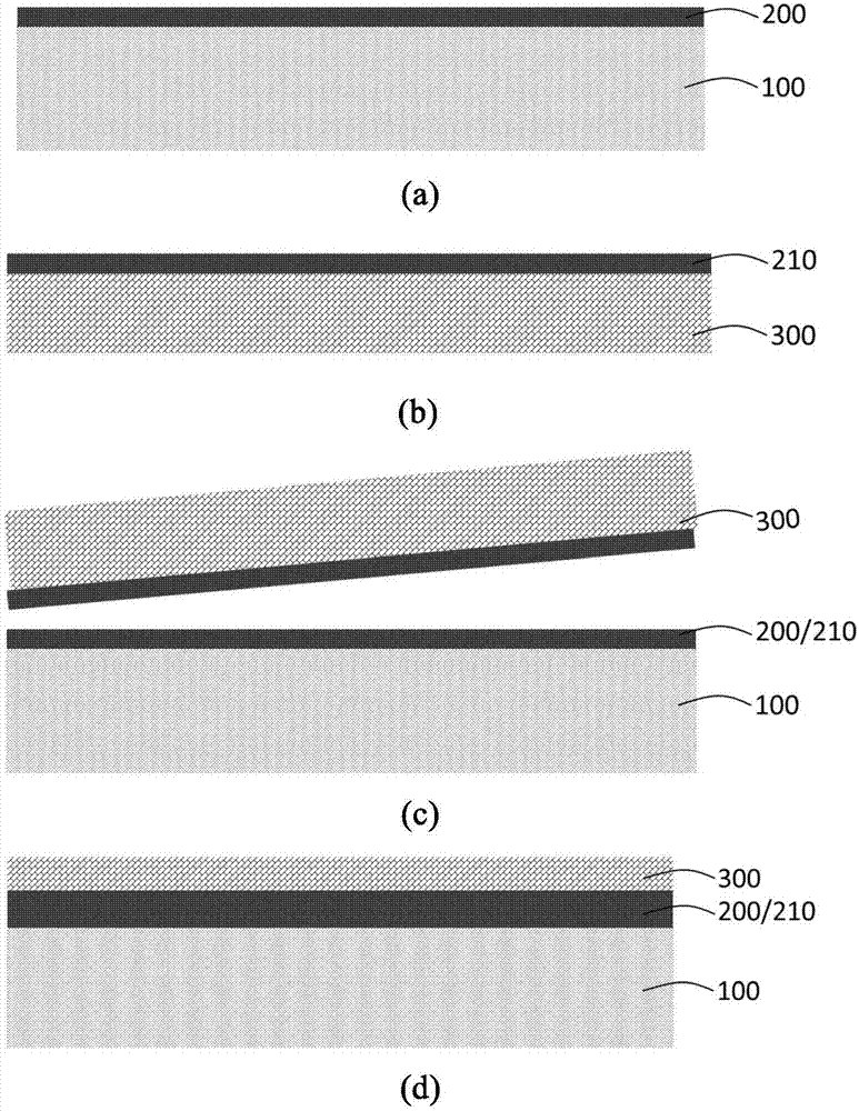
[0034] figure 2 It is a flow chart of the preparation process of the temperature-compensated surface acoustic wave resonator of the present invention. like figure 2 As shown, the present invention also proposes a method for preparing the temperature-compensated surface acoustic wave resonator used in Example 1, the preparation method comprising the following steps:

[0035] (a) Prepare a substrate 100 polished on one or both sides, with the polished side up, for standard cleaning. Then deposit a layer of adhesive material on the surface of the silicon wafer to form a first adhesive film layer 200 , the material of the first adhesive film layer 200 can be, for example, silicon dioxide, silicon oxynitride and the like. like figure 2 (a) shown.

[0036] (b) Deposit a layer of adhesive film material on the piezoelectric material substrate 300 to form the second adhesive film layer 210, the deposition process of the second adhesive film layer 210 is the same as that of the f...


PUM

PropertyMeasurementUnit
Thicknessaaaaaaaaaa

Abstract

The invention provides a temperature compensation surface acoustic wave resonator. The temperature compensation surface acoustic wave resonator comprises a substrate, a piezoelectric material base plate located on the substrate and an interdigital structure formed on the piezoelectric material base plate, wherein a bonding layer is arranged between the substrate and the piezoelectric material base plate to form a composite base plate. The temperature compensation surface acoustic wave resonator has the advantages that the process difficulty can be effectively reduced, the process stability and reliability are improved, the product yield is increased, the frequency temperature coefficient is decreased, and the performance of the device is improved.

Description

technical field [0001] The invention relates to a novel surface acoustic wave resonator, in particular to a temperature-compensated surface acoustic wave resonator formed based on a bonding process and a preparation method thereof. Background technique [0002] With the development of wireless communication applications, people have higher and higher requirements for data transmission speed. In the field of mobile communication, the first generation is analog technology, the second generation realizes digital voice communication, the third generation (3G) is characterized by multimedia communication, and the fourth generation (4G) increases the communication rate to 1Gbps and reduces the delay By 10ms, the fifth generation (5G) is a new generation of mobile communication technology after 4G. Although the technical specifications and standards of 5G have not yet been fully clarified, compared with 3G and 4G, its network transmission rate and network capacity will be greatly i...

Claims


Application Information

Patent Timeline
IPC IPC(8): H03H9/02H03H9/05H03H9/145
CPCH03H9/02543H03H9/02834H03H9/0538H03H9/14538H03H9/14544Y02D30/70
Inventor 张树民陈海龙王国浩郑贵珍汪泉
Owner HANGZHOU SAPPLAND MICROELECTRONICS TECH CO LTD
Learn More