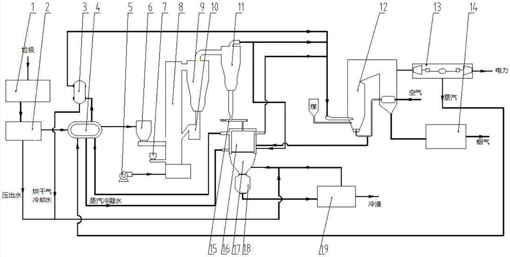
Garbage gasification coupling coal-fired power plant power generating apparatus and power generating process

A coal-fired power station and power generation device technology, which is applied in the direction of gasification process, combined combustion mitigation, petroleum industry, etc., can solve the problems of low slag utilization rate, high equipment investment, groundwater pollution, etc., and achieve the reduction of organic component content, system equipment Low investment and lower melting temperature

Pending Publication Date: 2017-11-24
HEFEI DEBO BIOENERGY SCI & TECH
View PDF6 Cites 13 Cited by
  • Summary
  • Abstract
  • Description
  • Claims
  • Application Information

AI Technical Summary

Problems solved by technology

The long-term development of the landfill method and the composting method is restricted by the disadvantages of low efficiency, serious groundwater pollution, and a large area; due to the weak domestic waste classification infrastructure and the weak concept of waste classification by citizens, the long way to go for recycling waste treatment is currently not possible. Popularization and application; the incineration method is increasingly valued and promoted due to its efficient energy utilization, 70-90% reduction in waste volume after incineration, and high waste disposal efficiency.
[0003] However, conventional waste incineration power generation exists: the gas produced by waste incineration has high content of dioxins and nitrogen oxides, and the utilization rate of slag generated after incineration is low. Low, high equipment investment and other issues

Method used


Image

  • Garbage gasification coupling coal-fired power plant power generating apparatus and power generating process

Examples


Embodiment 1

[0045] After the garbage is sorted by the sorting device, 50% of plastics, 5% of wood chips and paper, 45% of biological and kitchen waste, and a moisture content of 35%. After extrusion, dehydration, granulation and drying, the moisture content is reduced to 20%. density≤3cm, 1.0mm river sand is added to the gasifier from the bed material hopper, 0.8mm dolomite is added according to dolomite:garbage=0.3:1 (kg / kg), the operating temperature of the gasifier is 650°C, and the inner flow of the furnace is controlled The melting speed is 3.5m / s, the melting chamber temperature is 950°C, the steam pressure generated in the melting chamber is 0.75MPa, and the dioxin content in the gas is 0.008ng / Nm3. The high-temperature gas generated by the gasifier and the high-temperature flue gas generated by the melting chamber are sent to the coal-fired boiler for coupling power generation. The temperature of the steam extracted from the steam power generation device is 250°C, and the dioxin co...

Embodiment 2

[0047] After the garbage is sorted by the sorting device, 70% of plastics, 5% of wood chips and paper, 25% of biological and kitchen waste, and a moisture content of 20%. After extrusion, dehydration, granulation and drying, the moisture content is reduced to 9%. Density ≤ 3cm, 0.9mm river sand is added to the gasifier from the bed material hopper, 0.6mm limestone is added according to limestone:garbage=0.6:1 (kg / kg), the operating temperature of the gasifier is 850°C, and the fluidization speed in the furnace is controlled 3.0m / s, the melting chamber temperature is 900°C, the steam pressure generated in the melting chamber is 0.5MPa, and the dioxin content in the gas is 0.01ng / Nm3. The high-temperature gas generated by the gasification furnace and the high-temperature flue gas generated by the melting chamber are sent to the coal-fired boiler for coupled power generation. The slag is sent to building material processing plants or landfills.

Embodiment 3

[0049] After the garbage is sorted by the sorting device, 25% of plastics, 15% of wood chips and paper, 60% of biological and kitchen waste, and a moisture content of 50%. Density ≤ 3cm, 1.5mm river sand is added to the gasifier from the bed material hopper, 1.0mm calcium oxide particles are added according to calcium oxide particles: garbage = 0.2: 1 (kg / kg), the operating temperature of the gasifier is 600°C, and the furnace is controlled The internal fluidization velocity is 3.0m / s, the melting chamber temperature is 1150°C, the steam pressure generated in the melting chamber is 1.0MPa, and the dioxin content in the gas is 0.007ng / Nm3. The high-temperature gas generated by the gasification furnace and the high-temperature flue gas generated by the melting chamber are sent to the coal-fired boiler for coupling power generation. The slag is sent to building material processing plants or landfills.


PUM

PropertyMeasurementUnit
particle diameteraaaaaaaaaa

Abstract

The invention discloses a garbage gasification coupling coal-fired power plant power generating apparatus and power generating process. The power generating apparatus comprises a garbage primary treatment unit, a garbage pyrolysis gasification unit, a garbage flying ash melting unit and a coal-fired power plant power generating unit. The power generating process comprises the following steps: pyrolysing and gasifying garbage by utilizing a circulating fluidized bed gasification furnace to generate high-temperature fuel gas, sending the high-temperature fuel gas into a coal-fired boiler, burning and coupling the high-temperature fuel gas to generate power, melting the garbage flying ash in a melting chamber, chilling, and using as a construction material or directly burying. The fuel gas obtained by pyrolysing and gasifying the garbage and high-temperature smoke generated by the molten slag are coupled with the coal-fired power station to generate the power, and the power generating efficiency is high; by adding dechloridation co-solvent in a gasification furnace, the emission amount of dioxin is far less than the international standard; and the garbage flying ash of the invention is molten and then chilled to form glassy slag which can be used as the construction material or can be directly buried, so that the floor occupation area is small, no heavy metal is leached, and safety and environmental protection can be realized.

Description

technical field [0001] The invention belongs to the technical field of waste utilization, and in particular relates to a waste gasification coupled coal-fired power station power generation device and a power generation process. Background technique [0002] In recent years, with the development of my country's economy, the improvement of people's living standards, and the acceleration of urbanization, the discharge of urban waste has increased rapidly. It is estimated that by 2020, the annual output of urban waste in my country will reach 210 million tons. At present, the harmless treatment methods of garbage mainly include: landfill method, composting method, incineration method, and resource treatment. The long-term development of the landfill method and the composting method is restricted by the disadvantages of low efficiency, serious groundwater pollution, and a large area; due to the weak domestic waste classification infrastructure and the weak concept of waste class...

Claims


Application Information

Patent Timeline
Patent Type & Authority Applications(China)
IPC IPC(8): C10J3/20C10J3/30C10J3/72C10J3/84
CPCC10J3/20C10J3/30C10J3/72C10J3/84C10J2300/1675C10J2300/1807C10J2300/0983C10J2300/0946C10J2300/0906C10J2300/0909C10J2300/1606C10J2300/1634Y02E20/18
Inventor 张守军王勤辉张齐生周建斌鲁万宝赵成武冯干李益瑞吴银龙张守峰胡鹏程东海
Owner HEFEI DEBO BIOENERGY SCI & TECH
Why Eureka
Try Eureka