
Method for testing electroplating current efficiency by using square Hull cell

A current efficiency, square technology, applied in the electrolysis process, electrolysis components, weighing by removing certain components, etc., can solve the problems of large deviation, large difference in cathode current density distribution, troublesome production of electricity meter, etc., to improve the accuracy The effect of high speed, simple operation and low cost

Inactive Publication Date: 2017-11-21
东莞市同欣新材料有限公司
View PDF7 Cites 1 Cited by
  • Summary
  • Abstract
  • Description
  • Claims
  • Application Information

AI Technical Summary

Problems solved by technology

The disadvantage of the traditional method is that, first, the production of the coulometer is cumbersome, and it is necessary to make the coulometer plating tank, configure the solution, and select the corresponding electrodes; second, if the coulometer is used in conjunction with the actual plating tank, the coulometer plating tank The volume will also be very large; third, the traditional method does not have small test equipment. If the Hall cell is used for testing, the difference in the distribution of the cathode current density is large. For the electroplating type with a relatively uniform distribution of the actual cathode current density, the deviation will be relatively large ; Fourth, in the traditional method, the reason why the electricity meter is used is that the precise control of the plating electricity cannot be effectively achieved in the past technology

Method used


Image

  • Method for testing electroplating current efficiency by using square Hull cell
  • Method for testing electroplating current efficiency by using square Hull cell

Examples


Embodiment Construction

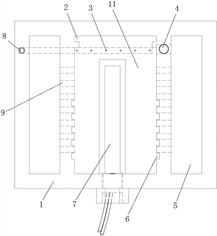
[0024] In this example, refer to figure 1 and figure 2 , the method for utilizing square Hall cell to test electroplating current efficiency is carried out in the following steps,

[0025] 1) Sampling. Before sampling, fully stir the plating solution, and sample the plating solution from different parts of the plating tank, and use it after mixing;

[0026] 2) Remove the coating on the side of the test piece that needs to be plated, use 3000# fine sandpaper or a scouring pad to polish the brass test piece in one direction, and dry it at 50ºC for later use;

[0027] 3) Take 500ml of the plating solution sampled in step 1) and put it into the square Hall tank, heat the plating solution to the process temperature, and turn on the air stirring during the heating process to avoid local overheating and decompose the additive; the plating solution cannot be heated If the temperature is too high, it cannot fully reflect the original state of the plating solution even after cooling;...


PUM


Abstract

The invention discloses a method for testing the electroplating current efficiency by using a square Hull cell. The method comprises the following steps: taking a sample, polishing a test piece, placing the above sampled plating solution in the square Hull cell, heating the plating solution to a process temperature, cutting the test piece to form a required size, inserting an anode plate into an anode slot in the middle of the square Hull cell, connecting the positive electrode of a power supply to the anode plate, connecting the negative electrode of the power supply to the test piece, starting the power supply and an air pump, turning off the power supply when a predetermined time is reached, taking out and flushing the test piece, calculating the practical deposition mass of a plating layer and the mass of a plating layer deposited at a current efficiency of 100%, and calculating the current efficiency. The test method using the square Hull cell as a test device and designed according to the characteristics of the square Hull cell can be used to rapidly measure the practical current efficiency in order to accurately control the thickness of the plating layer, and the method also has the advantages of simplicity in operation, high efficiency, low cost, and realization of automatic implementation by electroplating manufacturers without a third party monitoring mechanism.

Description

technical field [0001] The invention relates to the technical field of electroplating, in particular to a method for testing electroplating current efficiency by using a Hall cell device. Background technique [0002] In the electroplating industry, the current efficiency of many electroplating processes is greatly affected by the composition of the plating solution and process conditions, and most electroplating manufacturers use the time method to control the thickness of the electroplating, but if the current efficiency cannot be determined, it is difficult to control the thickness of the electroplating layer . The traditional method of testing the current efficiency of the electroplating solution is to first have a device capable of calculating the actual energized electricity, generally using a copper or silver electricity meter, and then connect the anode and cathode of the tested plating tank in series with the electricity meter, and when a certain amount of electrici...

Claims


Application Information

Patent Timeline
IPC IPC(8): G01N5/04C25D21/02C25D17/00C25D21/12
CPCG01N5/04C25D17/00C25D21/02C25D21/12
Inventor 王庆浩樊雄
Owner 东莞市同欣新材料有限公司
Learn More