
One-step pelletizer

A granulator, fluidized bed granulation technology, applied in the direction of mixer, special binder granulation, powder suspension granulation, etc., can solve problems such as dead angle, uneven granulation, dead bed, etc., to achieve efficiency and The effect of quality improvement, overall granulation uniformity, and dead angle reduction

Pending Publication Date: 2017-09-01
周建南
View PDF15 Cites 1 Cited by
  • Summary
  • Abstract
  • Description
  • Claims
  • Application Information

AI Technical Summary

Problems solved by technology

[0003] At present, we know that the existing one-step granulator has insufficient overall setting of the internal fluidized bed, and the internal wind field is uneven, which is mainly caused by the insufficient design of the internal differentiation plate, which leads to the fluidization of the material inside the machine 1. The granulation is not uniform, and it is easy to produce dead angles inside, which will cause bed collapse and dead bed phenomenon during granulation, which will seriously affect the quality and efficiency of granulation; therefore, the applicant based on the existing one-step granulator A further improvement is proposed above, and a one-step granulator is designed to meet the needs of the existing market

Method used


Image

  • One-step pelletizer
  • One-step pelletizer
  • One-step pelletizer

Examples


Embodiment 1

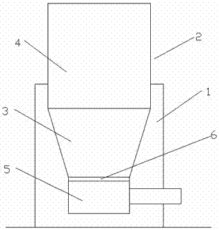
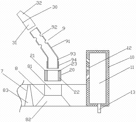
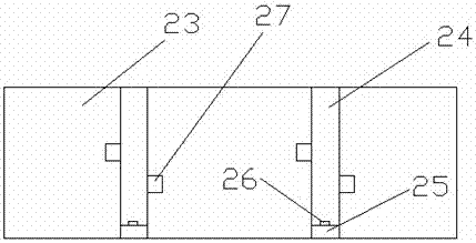
[0028] Such as Figure 1-3 As shown, the present invention relates to a one-step granulator, comprising a frame 1, on which a fluidized bed granulation chamber 2 is arranged, and the fluidized bed granulation chamber 2 includes a lower material bin 3 and an upper The granulation bin 4 is provided with an air inlet bin 5 at the bottom of the material bin 3, and an air flow distribution plate 6 is arranged between the air inlet bin 5 and the material bin 3. The flow mentioned in the present invention The chemical bed granulation chamber 2 is the prior art, including its material bin 3 and the granulation bin 4, which are all prior art, and will not be repeated here. The present invention improves the air flow distribution plate 6 inside it, and the air flow distribution The plate 6 includes a plate body 7, and a plurality of air holes 8 are formed on the plate body 7, and an air flow pipe 9 is arranged on the air air hole 8, and the flow direction of the air flow out of the air ...

Embodiment 2

[0035] Such as Figure 4As shown, the difference from Embodiment 1 is that the nozzle 30 in the present invention includes a connecting pipe 31, and the connecting pipe 31 is threadedly connected to the end of the air flow pipe 9, and the end of the connecting pipe 31 is The sealing end 33 forms an air outlet groove 34 around the wall body of the end, so that different airflows are formed around the whole area, and the overall material and adhesive are mixed more uniformly and fully, and the collapse of the bed and the death of the bed are not easy to occur. Phenomenon, so that the granulation is more uniform, to ensure product quality.


PUM


Abstract

The invention discloses a one-step pelletizer, which comprises a frame, wherein a fluidized bed pelletizing chamber is arranged on the frame, the fluidized bed pelletizing chamber comprises a lower material bin and an upper pelletizing bin, an air inlet bin is arranged at the bottom of the material bin, an air flow distribution plate is arranged between the air inlet bin and the material bin, the air flow distribution plate comprises a plate body, a plurality of vent holes are formed on the plate body, an airflow tube is arranged on each vent hole, an auxiliary ring is formed on the circumference of the plate body, the interior of the auxiliary ring is a hollow cavity, a plurality of outlet holes are formed on the inner side wall of the auxiliary ring, and the outlet holes are communicated with the hollow cavity; and an air inlet pipe is arranged at the bottom end of the auxiliary ring. The one-step pelletizer of the invention can solve the shortcomings in the prior art, and in the interior of the fluidized bed pelletizing chamber, the pellets are uniform, the dead angle is reduced, and the pelletizing efficiency and quality are improved.

Description

technical field [0001] The invention relates to the field of medical machinery and equipment, in particular to a one-step granulator. Background technique [0002] The working principle of the one-step granulator: the powdery material is put into the closed container of the hopper, and due to the action of the hot air flow, the powder is suspended and circulated in a fluidized state to achieve uniform mixing. Powder, the powder is condensed into loose small particles. At the same time of granulation, due to the efficient drying of the hot air flow, the water is continuously evaporated, and the powder is continuously solidified. The process is repeated to form ideal, uniform microporous spherical particles. , complete the three processes of mixing, granulation and drying in one container. [0003] At present, we know that the existing one-step granulator has insufficient overall setting of the internal fluidized bed, and the internal wind field is uneven, which is mainly cau...

Claims


Application Information

Patent Timeline
IPC IPC(8): B01J2/16B01J2/28B01F13/02B01F33/40
CPCB01J2/16B01J2/28B01F33/405B01F33/4094B01F33/409
Inventor 周建南
Owner 周建南
Learn More