
Method for acquiring main energy source required by supercritical carbon dioxide power generation in cement plant

A technology of carbon dioxide and acquisition method, applied in the fields of environmental protection and energy

Inactive Publication Date: 2017-08-18
长沙紫宸科技开发有限公司
View PDF6 Cites 0 Cited by
  • Summary
  • Abstract
  • Description
  • Claims
  • Application Information

AI Technical Summary

Problems solved by technology

[0006] The technical problem to be solved by the present invention is that the clinker production system for the high-energy-consuming cement industry is essentially a high-temperature thermochemical reaction kiln system, and the actual energy consumption in clinker production is much higher than that required for thermochemical reaction equilibrium. A large amount of waste heat is continuously generated in the production process, and the high-temperature heat energy of some high-temperature equipment and high-temperature materials has objectively caused some adverse effects. It provides a combination solution to the high-temperature heat energy generated in the cement clinker production process. Specific adverse impact issues, low investment CO 2 The energy storage device stores the high-temperature radiation heat and / or conduction heat energy generated by high-temperature equipment / high-temperature materials in the cement production process, and simply and economically obtains the main high-temperature energy required for supercritical carbon dioxide power generation in cement plants

Method used


Image

  • Method for acquiring main energy source required by supercritical carbon dioxide power generation in cement plant
  • Method for acquiring main energy source required by supercritical carbon dioxide power generation in cement plant
  • Method for acquiring main energy source required by supercritical carbon dioxide power generation in cement plant

Examples


Embodiment 1

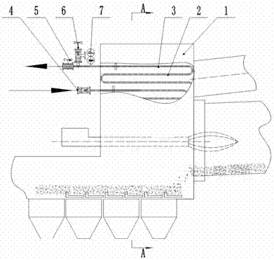
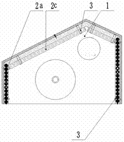
[0068] A method adapted to the supercritical CO 2 Method for generating the required energy: Built-in CO in the kiln hood 2 The energy storage device directly stores the strong radiant heat energy in the kiln hood of the dry process rotary kiln production line at a normal temperature of 800°C to 1450°C and higher, and uses the stored high-temperature heat energy to convert CO 2 Conversion to high-energy-density high-pressure thermal supercritical CO 2 fluid, as supercritical CO 2 The main energy source for power generation.

[0069] The kiln hood built-in CO 2 energy storage devices, such as Figure 1a-Figure 1b As shown, it mainly includes kiln head cover 1, CO 2 Fluid energy storage mechanism 2, hanger 3, check valve 4, regulating valve 5, safety valve 6 and temperature and pressure sensor 7, the CO 2 The fluid energy storage mechanism 2 includes a disc-type hollow tube heat exchanger 2a and a box-type heat exchanger 2c. The disc-type hollow tube heat exchanger 2a is f...

Embodiment 2

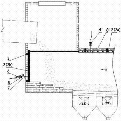
[0072] In order to solve the unfavorable effects of high-temperature hot clinker sintering and making snowmen in the grate cooler of the cement plant, it is obtained and adapted to supercritical CO 2 Method to generate energy required for power generation: Built-in CO with a grate cooler 2 The energy storage device directly stores the strong radiation / conduction heat energy of the clinker in the grate cooler of the dry-process rotary kiln production line at 200°C to 1350°C, and uses the stored high-temperature heat energy to convert CO 2 Conversion to high-energy-density high-pressure thermal supercritical CO 2 Fluid energy, as supercritical CO 2 the primary energy source for power generation;

[0073] The grate cooler built-in CO 2 energy storage devices, such as Figure 2a-Figure 2b As shown, it mainly includes grate cooler 8, CO 2 Fluid energy storage mechanism 2, hanger 3, check valve 4, regulating valve 5, safety valve 6 and temperature and pressure sensor 7, the CO ...

Embodiment 3

[0076] A kind of supercritical CO 2 Method of generating energy required for power generation: Built-in CO in the kiln tail smoke chamber 2 The energy storage device directly stores the high-temperature radiation / conduction heat energy in the kiln tail smoke chamber of the cement production line at 850°C to 1200°C, and uses the stored high-temperature heat energy to convert CO 2 Conversion to high-energy-density high-pressure thermal supercritical CO 2 Fluid energy, as supercritical CO 2 The energy generated by the generating set;

[0077] The kiln tail smoke chamber built-in CO 2 energy storage devices, such as image 3 As shown, it mainly includes kiln tail smoke chamber 9, CO 2 Fluid energy storage mechanism 2, hanger 3, check valve 4, regulating valve 5, safety valve 6 and temperature and pressure sensor 7, the CO 2 The fluid energy storage mechanism 2 includes a disc-type hollow tube heat exchanger 2a and a plate-type heat exchanger 2b, and the disc-type hollow tube...


PUM


Abstract

The main energy acquisition method required for supercritical carbon dioxide power generation in cement plants, the process and equipment characteristics of high-temperature thermochemical reaction kiln systems using clinker in cement plants, and CO 2 The energy storage device directly stores part of the heat energy of strong radiation / conduction of high-temperature equipment and / or high-temperature materials, and solves the specific adverse effects caused by the high-temperature heat energy radiated / conducted by high-temperature equipment and / or high-temperature materials. The high temperature heat energy converts CO 2 Fluid conversion to high-pressure hot supercritical CO with high energy density 2 fluid, as supercritical CO 2 The main energy source for generator sets to generate electricity. The present invention solves the adverse effects of various types of high-temperature heat energy in various links in the cement clinker production process on the kiln system operating conditions, clinker cooling quality, equipment safety and staff safety, etc., and develops a supercritical CO 2 A series of high-quality high-temperature energy sources for high-efficiency power generation by the power generation system, the method is simple and has industrial practicability.

Description

technical field [0001] The present invention relates to the field of environmental protection and energy technology, in particular to a combination solution to some specific adverse effects caused by various types of high-temperature heat energy in each link of a cement production line, and to economically obtain supercritical CO in cement plants. 2 A method for the primary high-temperature energy source required for power generation. Background technique [0002] As we all know, cement production enterprises are recognized as high-energy-consuming and high-polluting enterprises, and are one of the main sources of carbon dioxide emissions. They not only consume a lot of primary energy (coal) and secondary energy (electricity). CO from cement production 2 Emissions can be divided into CO2 from decomposition of raw material carbonate and combustion of fuel 2 direct emissions and indirect emissions from external electricity consumed in the production process. According to th...

Claims


Application Information

Patent Timeline
IPC IPC(8): F27D17/00
CPCF27D17/004F27D2017/007
Inventor 尹小林
Owner 长沙紫宸科技开发有限公司
Learn More