Thermal superconduction fin type radiator and electrical equipment chassis

A technology of electrical equipment and thermal superconductivity, which is applied in the structural parts of electrical equipment, electrical components, cooling/ventilation/heating transformation, etc., can solve the problem of not meeting the heat dissipation requirements of high heat flux density and high power modules, affecting air convection and heat dissipation, Problems such as suspension and fixation are difficult to achieve good work adaptability, convenient and flexible manufacturing, and light weight

Pending Publication Date: 2017-08-15
ZHEJIANG JIAXI TECH CO LTD
View PDF7 Cites 1 Cited by
  • Summary
  • Abstract
  • Description
  • Claims
  • Application Information

AI Technical Summary

Problems solved by technology

[0007] In view of the above-mentioned shortcomings of the prior art, the purpose of the present invention is to provide a thermal superconducting finned radiator and an electrical equipment chassis, which are used to solve the problem of large volume and heavy weight of the aluminum profile radiator in the prior art. 1. The heat dissipation ability is poor, which cannot meet the heat dissipation requirements of high heat flux density and high power modules; and the existing heat sink can only be installed on the back of the electrical equipment chassis, which affects air convection and heat dissipation, and is difficult to hang and fix. question

Method used


Image

  • Thermal superconduction fin type radiator and electrical equipment chassis
  • Thermal superconduction fin type radiator and electrical equipment chassis
  • Thermal superconduction fin type radiator and electrical equipment chassis

Examples


Embodiment 1

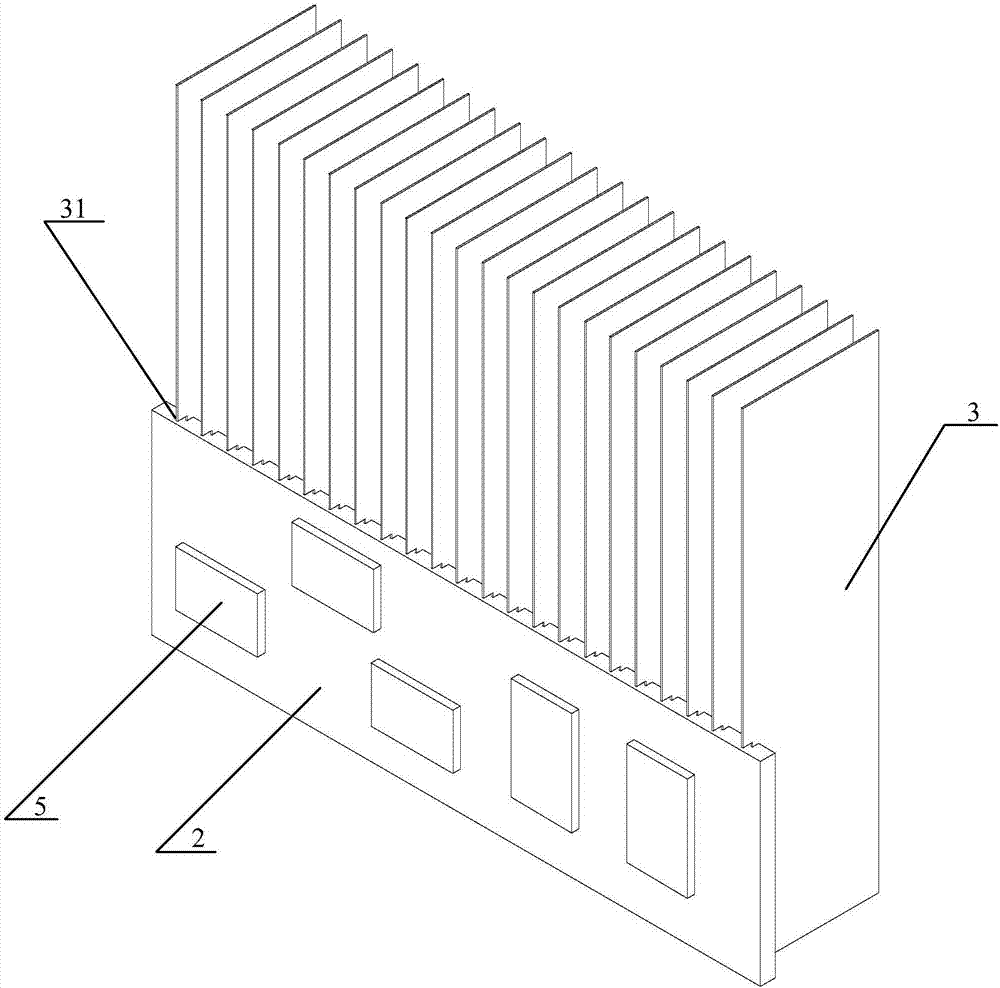
[0062] see Figures 2 to 7 , the present invention provides a thermal superconducting finned radiator, said thermal superconducting finned radiator comprising: radiator substrate 2; several thermal superconducting fins 3, said thermal superconducting fins 3 is inserted on the surface of the heat sink substrate 2; the thermal superconducting heat dissipation fin 3 is a composite plate structure, and a thermal superconducting circuit 31 of a specific shape is formed inside the thermal superconducting heat dissipation fin 3. The thermal superconducting pipeline 31 is a closed pipeline, and the thermal superconducting pipeline 31 is filled with a heat transfer working medium 34; the projected area of ​​several thermal superconducting cooling fins 3 in the plane where the radiator substrate 2 is located larger than the area of ​​the radiator substrate 2 . The present invention adopts the thermal superconducting fins 3 to replace conventional heat sinks in the prior art, so that th...

Embodiment 2

[0072] see Figure 8 , the present invention also provides a thermal superconducting fin radiator, the structure of the thermal superconducting fin radiator described in this embodiment is the same as the structure of the thermal superconducting fin radiator described in Embodiment 1 roughly the same, the difference between the two is: the length direction of the thermal superconducting heat dissipation fins 3 in Embodiment 1 is consistent with the width direction of the heat sink substrate 2, and the length of the thermal superconducting heat dissipation fins 3 greater than the width of the radiator substrate 2; and in this embodiment, the length direction of the thermal superconducting fins 3 is consistent with the longitudinal direction of the radiator substrate 2, and the thermal superconducting fins 3 The length is greater than the length of the heat sink substrate 2 .

Embodiment 3

[0074] see Figure 9 and Figure 10, the present invention also provides a thermal superconducting fin radiator, the structure of the thermal superconducting fin radiator described in this embodiment is the same as the structure of the thermal superconducting fin radiator described in Embodiment 1 Roughly the same, the difference between the two is: compared with the thermal superconducting fin radiator described in Embodiment 1, the thermal superconducting fin radiator in this embodiment has added a reinforcing buckle 4, so The reinforcement buckle 4 is at least located on one side of the thermal superconducting fins 3, and extends along the arrangement direction of the thermal superconducting fins 3, and is connected with each thermal superconducting fin 3 The sides are fixedly connected. in, Figure 8 In the above, the reinforcement buckle 4 is taken as an example, and the reinforcement buckle 4 is located on the same side as the radiator substrate 2. Of course, in other...


PUM


Abstract

The invention provides a thermal superconduction fin type radiator and an electrical equipment chassis. The thermal superconduction fin type radiator comprises a radiator substrate and a plurality of thermal superconduction radiating fins, wherein the thermal superconduction radiating fins are inserted on the surface of the radiator substrate; the thermal superconduction radiating fins are of a composite plate type structure, a special-shaped thermal superconduction pipeline is formed in each thermal superconduction radiating fin, each thermal superconduction pipeline is a closed pipeline, and each thermal superconduction pipeline is filled with a heat transferring working medium; and a projection area of the plurality of thermal superconduction radiating fins in a plane where the radiator substrate locates is greater than an area of the radiator substrate. The thermal superconduction fin type radiator has the advantages of fast thermal conduction, high fin efficiency, flexible and diverse structure, high radiating capacity and the like, and the fin efficiency does not vary with height, length and thickness of the thermal superconduction radiating fins; and the projection area of the plurality of thermal superconduction radiating fins in the plane where the radiator substrate locates is greater than the area of the radiator substrate, thus the weight of the thermal superconduction fin type radiator can be significantly reduced on the premise of ensuring the radiating capacity.

Description

technical field [0001] The invention relates to a radiator for heat dissipation of high-power electronic devices, in particular to a thermal superconducting fin radiator and an electrical equipment case. Background technique [0002] With the rapid development of power electronics technology, the requirements for modularization, integration, lightweight, low cost and high reliability are getting higher and higher. Therefore, in solar inverters, uninterruptible power supplies (UPS), charging piles, power MosFET (metal oxide semiconductor field effect transistor), Diode (diode), IGBT ( Insulated Gate Bipolar Transistors) and other power devices. As the integration of these power components is getting higher and higher, the power density is also increasing, and the heat generated by themselves during work is also increasing. If the heat generated by the power devices cannot be dissipated in time and quickly, it will lead to power failure. The temperature of the chip in the de...

Claims


Application Information

Patent Timeline
Patent Type & Authority Applications(China)
IPC IPC(8): H05K7/20
CPCH05K7/20409
Inventor 仝爱星斯奕超罗启洪
Owner ZHEJIANG JIAXI TECH CO LTD
Why Eureka
Try Eureka