
Anti-blocking segmented arrangement system for air pre-heaters

An air preheater and flue gas technology, applied in the field of boilers, can solve the problems of increasing the risk of low temperature corrosion of heat storage elements, air preheater corrosion and ash blocking, and increased ammonium hydrogen sulfate generation, etc. Improve and solve the problem of ash blocking and improve the effect of thermal efficiency

Pending Publication Date: 2017-08-01
XIAN THERMAL POWER RES INST CO LTD
View PDF0 Cites 3 Cited by
  • Summary
  • Abstract
  • Description
  • Claims
  • Application Information

AI Technical Summary

Problems solved by technology

In recent years, with the gradual implementation of ultra-low emission transformation, most coal-fired units in China have installed 3-layer denitration catalysts, which has improved the denitrification efficiency. 3 requirements, however, due to the increase in catalyst volume, SO in the flue gas 2 to SO 3 The conversion rate increases, the SO in the flue gas 3 When the concentration increases, under the condition that a certain amount of ammonia escapes, the amount of ammonium bisulfate at the outlet of the denitrification system will increase. When the flue gas temperature is in the range of 146°C to 230°C (at the heat storage element in the middle temperature section and low temperature section of the traditional air preheater) Ammonium bisulfate is in a liquid state. At this time, the liquid ammonium bisulfate binds the fly ash particles in the flue gas, causing the air preheater to corrode and block the ash.
In addition, due to the SO in flue gas 3 Increased concentration increases the acid dew point of flue gas and increases the risk of low-temperature corrosion of heat storage elements in the low-temperature section of the air preheater

Method used


Image

  • Anti-blocking segmented arrangement system for air pre-heaters

Examples


Embodiment Construction

[0022] The present invention will be described in further detail below in conjunction with the accompanying drawings.

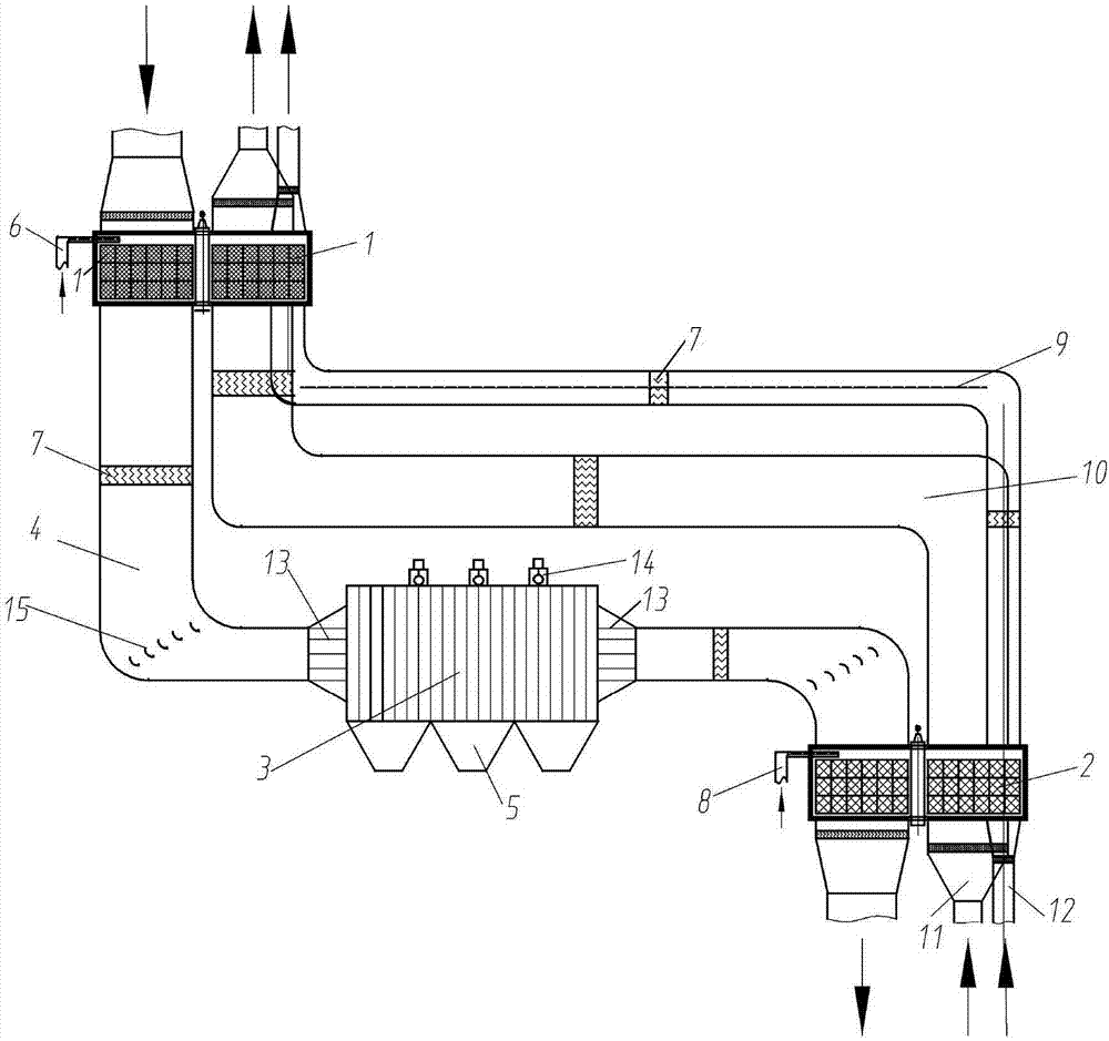
[0023] see figure 1 , the present invention proposes an anti-blocking type air preheater segmented arrangement system based on a different arrangement from the traditional air preheater. The purpose is to completely improve the working environment of the air preheater heat storage element without affecting the thermal efficiency of the boiler. , in order to deal with the common ash plugging problem in the air preheater after the SCR denitrification device is put into operation.

[0024] The system includes a high temperature air preheater 1, a high temperature electrostatic precipitator 3 and a low temperature air preheater 2. The low-temperature air preheater 2 is arranged in front of the low-temperature electric dust collector, and the high-temperature electric dust collector is arranged on the flue gas side between the high-temperature air preheater and t...


PUM

PropertyMeasurementUnit
Heightaaaaaaaaaa

Abstract

An anti-blocking segmented arrangement system for air pre-heaters comprises a high-temperature air pre-heater arranged behind a selective catalytic reduction (SCR) denitration device of a flue at the tail of a boiler; flue gas at the outlet of the high-temperature air pre-heater enters a high-temperature electrostatic precipitator through a flue; flue at the outlet of the high-temperature electrostatic precipitator enters a low-temperature air pre-heater through the flue for heat exchange; cold primary air enters the low-temperature air pre-heater through a cold primary air duct; supplied air enters the low-temperature air pre-heater through an air supply pipe; and the cold primary air and the supplied air absorb flue gas heat in the low-temperature air pre-heater and then enter a primary air side inlet and a supplied air side inlet of the high-temperature air pre-heater through an intermediate-temperate primary air pipeline and an intermediate-temperate air supply pipeline respectively. With the system, the problem of clogging of the air pre-heaters can be solved fundamentally, so that the temperature of the discharged flue gas can be effectively reduced, the temperature of the primary air and the temperature of secondary air can be increased, and the heat efficiency of the boiler can be improved.

Description

technical field [0001] The invention belongs to the field of boilers, and in particular relates to an anti-blocking type air preheater section arrangement system. Background technique [0002] Air preheater (hereinafter referred to as "air preheater") is an important equipment of power plant boilers, and its function is to use the heat of flue gas at the tail of the boiler to heat the air required for combustion. For the rotary air preheater, if the heat exchange capacity of the air preheater decreases, on the one hand, the exhaust gas temperature of the boiler will increase, the heat loss of the exhaust gas will increase, and the thermal efficiency of the boiler will decrease; on the other hand, the outlet heat of the air preheater will The temperature of the primary air decreases. If the outlet temperature of the coal mill is maintained under a given coal supply, the primary air volume will increase and the power consumption rate of the primary fan will increase. The redu...

Claims


Application Information

Patent Timeline
IPC IPC(8): F23L15/00F23J15/02
CPCF23J15/02F23L15/00F23J2217/102Y02E20/34
Inventor 党黎军杨辉
Owner XIAN THERMAL POWER RES INST CO LTD
Learn More