
A Large Dynamic Range Tunable Attenuator Based on Zero-Refraction Metamaterial

A large dynamic range, metamaterial technology, applied in waveguide-type devices, circuits, electrical components, etc., can solve the problems of low return loss, unsatisfactory accuracy, single mode, etc., to achieve increased return loss, large dynamic Adjustment range, the effect of improving performance

Active Publication Date: 2019-04-26
BEIJING UNIV OF CHEM TECH
View PDF4 Cites 0 Cited by
  • Summary
  • Abstract
  • Description
  • Claims
  • Application Information

AI Technical Summary

Problems solved by technology

[0005] The problem to be solved by the present invention is to overcome the shortcomings of the existing attenuator technology, such as low return loss, unsatisfactory precision and single mode, and provide an adjustable attenuator with high return loss and large dynamic range

Method used


Image

  • A Large Dynamic Range Tunable Attenuator Based on Zero-Refraction Metamaterial
  • A Large Dynamic Range Tunable Attenuator Based on Zero-Refraction Metamaterial
  • A Large Dynamic Range Tunable Attenuator Based on Zero-Refraction Metamaterial

Examples


Embodiment 1

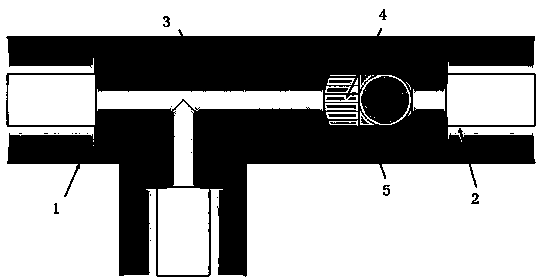
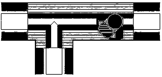
[0023] In order to further illustrate the effect of the structure of this device, we take a coaxial line with an outer radius of 3.5mm and an inner radius of 1.5mm as an example to make an attenuator in which the rotating rod is connected to the inner conductor. Cut off a section of the selected inner conductor of the coaxial line, and process the truncated rotating rod and the connection with the inner conductor as follows: Figure 5 The required shape is fixed by mechanical means. Then at the T-shaped intersection of the coaxial line, the zero-refractive-index metamaterial is filled between the inner and outer conductors, such as figure 1 As shown, the filling range needs to cover the T-shaped intersection and the area of ​​the rotating rod, but the rotating area of ​​the rotating rod needs to be reserved as an air slot.

[0024] According to the novel attenuator proposed by the present invention and its manufacturing method, Example 1 is obtained by simulation design using...

Embodiment 2

[0026] In order to further illustrate the effect of the structure of this device, as a comparison, we take the attenuator with an angle of 45 degrees between the rotating rod and the inner conductor as an example. Except for the position of the rotating rod, other structures, dimensions and materials of the attenuator are exactly the same as those in Example 1. same. The corresponding attenuation value is -22.984dB, the return loss is -32.101dB, and the standing wave ratio is 1.05 according to the simulation test.

Embodiment 3

[0028] In order to further illustrate the effect of the structure of this device, as a comparison, we take the example of making an attenuator in which the rotating rod is connected to the outer conductor, that is, the angle between the rotating rod and the inner conductor is 90 degrees. Except for the position of the rotating rod, other structures and dimensions of the attenuator And the material is exactly the same as Example 1. The corresponding attenuation value is -72.253dB, the return loss is -53.084dB, and the standing wave ratio is 1.00 through the simulation test.

[0029] Through the above three examples, the present invention can be explained. When the attenuation value is in the range of -5.145~-22.984dB, the voltage standing wave ratio (VSWR) is less than 1.23; when the attenuation value is in the range of -22.984~-72.253dB, the voltage standing wave The ratio (VSWR) is less than 1.05.


PUM


Abstract

The invention relates to an adjustable attenuator with high echo loss and large dynamic range based on a zero-refraction metamaterial. The adjustable attenuator comprises a T-shaped coaxial air line with three ports, an internal conductor is fractured at the port opposite to a matched load port, a rotation rod is arranged at the fracture position, one end of the rotation rod is rotatably connected with the internal conductor in a mechanical manner, the other end of the rotation rod rotates at any angle between the internal conductor and an outer conductor, the zero-refractive-index metamaterial is filled between the T-shaped junction, the internal conductor and the outer conductor, the metamaterial covers the rotation rod, and an air slot is reserved for a rotation area of the rotation rod. According to the attenuator, the attenuation can be controlled, and large dynamic adjusting range is provided; by employing the novel inserted metamaterial, the refractive index is zero, the echo loss of incident signals is increased, the reflectivity can be effectively reduced, interference with an input port front-end circuit is prevented, and the performance of the attenuator is effectively enhanced.

Description

technical field [0001] The invention relates to the field of microwave passive devices, in particular to a novel attenuator used in the communication industry, electronic equipment and instrument measurement and a manufacturing method thereof. Background technique [0002] The attenuator is a component widely used in microwave systems. It is used to attenuate the signal power. It is an essential key component in microwave electronic equipment. Distorted passive network. Generally, it is indicated by the decibel number of the attenuation and the ohm number of the characteristic impedance. In addition, the loss effect of any network on electromagnetic waves includes two parts: one is the energy absorbed and dissipated by the insertion material, called insertion loss; the other part is the energy reflected by it, called return loss. The invention discloses an attenuator which realizes high return loss and high dynamic range by inserting zero-refractive-index metamaterials and...

Claims


Application Information

Patent Timeline
Patent Type & Authority Patents(China)
IPC IPC(8): H01P1/22
CPCH01P1/225
Inventor 侯志灵张晨张凯伦
Owner BEIJING UNIV OF CHEM TECH
Learn More