
Manufacturing method and manufacturing equipment for thin film, display substrate and manufacturing method therefor

A production method and technology for display substrates, which are applied in semiconductor/solid-state device manufacturing, instruments, semiconductor devices, etc., can solve the problems of decreased material utilization efficiency, difficulty in ensuring thin film flatness, and uneven lighting brightness of devices, so as to improve the uniformity of light emission. The effect of consistency, thickness and improving utilization rate

Active Publication Date: 2017-07-14
BOE TECH GRP CO LTD
View PDF2 Cites 9 Cited by
  • Summary
  • Abstract
  • Description
  • Claims
  • Application Information

AI Technical Summary

Problems solved by technology

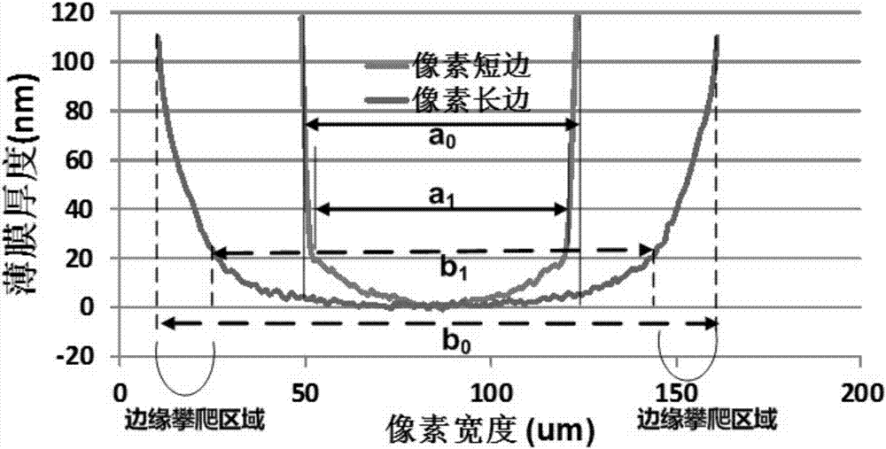
[0006] In view of this, the present invention provides a thin film manufacturing method, manufacturing equipment, display substrate and its manufacturing method, which are used to solve the serious climbing phenomenon of ink on the edge of the pixel when the thin film in the pixel is formed by the method of the solution process, thereby It is difficult to ensure the flatness of the formed film, resulting in uneven lighting brightness of the device, and the problem that the utilization efficiency of the material is greatly reduced

Method used


Image

  • Manufacturing method and manufacturing equipment for thin film, display substrate and manufacturing method therefor
  • Manufacturing method and manufacturing equipment for thin film, display substrate and manufacturing method therefor
  • Manufacturing method and manufacturing equipment for thin film, display substrate and manufacturing method therefor

Examples


Embodiment Construction

[0037] In order to make the purpose, technical solutions and advantages of the embodiments of the present invention more clear, the following will clearly and completely describe the technical solutions of the embodiments of the present invention in conjunction with the drawings of the embodiments of the present invention. Apparently, the described embodiments are some, not all, embodiments of the present invention. All other embodiments obtained by those skilled in the art based on the described embodiments of the present invention belong to the protection scope of the present invention.

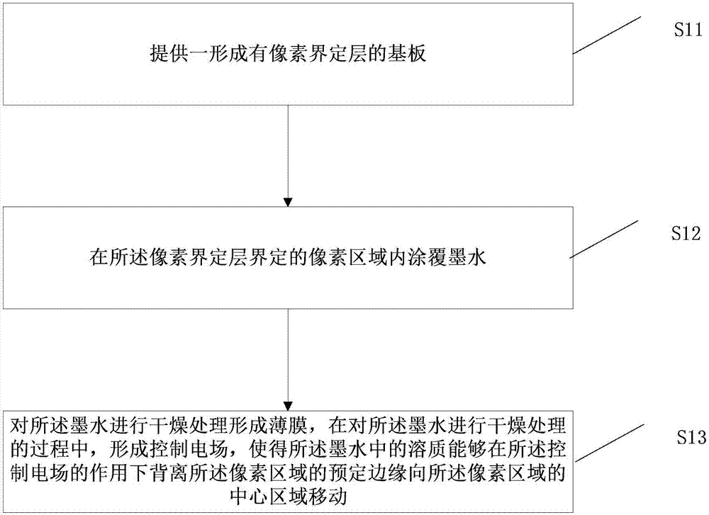
[0038] Please refer to image 3 , image 3 It is a schematic flow chart of a method for manufacturing a thin film according to an embodiment of the present invention, the method comprising:

[0039] Step S11: providing a substrate on which a pixel defining layer (PDL) is formed;

[0040] Step S12: coating ink in the pixel area defined by the pixel defining layer;

[0041] Specifically, ...


PUM


Abstract

The invention provides a manufacturing method and manufacturing equipment for a thin film, a display substrate and a manufacturing method therefor. The manufacturing method for the thin film comprises the steps of providing a substrate formed with a pixel defining layer; coating a pixel region defined by the pixel defining layer with ink; and performing drying treatment on the ink to form a thin film, wherein a control electric field is formed in the drying treatment process of the ink, so that solute in the ink can move to the central region of the pixel region in a direction deviating from the predetermined edge of the pixel region under the effect of the control electric field, so as to resist a pinning effect of the pixel defining layer, weaken a climbing phenomenon of the ink on the pixel edge region, enable the thicknesses of the thin film in each position of the pixel region to be consistent, and play a planarization effect, thereby improving the light emitting uniformity of a device equipped with the thin film, and further improving the efficiency and prolonging the service life of the device.

Description

technical field [0001] The invention relates to the field of display technology, in particular to a thin film manufacturing method, manufacturing equipment, a display substrate and a manufacturing method thereof. Background technique [0002] In the display field of electroluminescent devices, the thin film deposition of functional layers (such as light-emitting layers) is usually performed by solution process. Such solution processes include, but are not limited to, inkjet printing, spin coating, screen printing, and transfer printing, among others. An essential step in these wet film-forming processes is that the solvent needs to be removed through a subsequent drying process, so that the solute is dried to form the desired film. And this drying process to remove the solvent has a crucial influence on the morphology of the formed film. For optoelectronic display devices, the poor morphology and uniformity of the dry film have a great impact on the life of the device and ...

Claims


Application Information

Patent Timeline
Patent Type & Authority Applications(China)
IPC IPC(8): H01L51/56G02F1/1335
CPCG02F1/133514G02F1/133516H10K71/441H10K59/122H10K59/131H10K71/00
Inventor 代青
Owner BOE TECH GRP CO LTD
Learn More