
Special tool for coating face gluing layer on stretching net of surface mount technology (SMT) laser template

A special tool and laser template technology, applied in the direction of coating, liquid coating device on the surface, etc., can solve the problems of large consumption of masking tape, different width of the surface adhesive layer, labor and time-consuming masking tape, etc. Achieve the effect of anti-mesh degumming, uniform and consistent thickness, and improve production efficiency

Active Publication Date: 2012-11-14
天津光韵达光电科技有限公司
View PDF5 Cites 18 Cited by
  • Summary
  • Abstract
  • Description
  • Claims
  • Application Information

AI Technical Summary

Problems solved by technology

[0005] The present invention discloses an SMT laser template stretching net to coat the surface glue layer in order to solve the technical problems of labor-intensive and time-consuming pasting of the masking tape in the existing surface glue layer coating process, large consumption of masking tape and uneven width of the surface glue layer. special tool for

Method used


Image

  • Special tool for coating face gluing layer on stretching net of surface mount technology (SMT) laser template
  • Special tool for coating face gluing layer on stretching net of surface mount technology (SMT) laser template
  • Special tool for coating face gluing layer on stretching net of surface mount technology (SMT) laser template

Examples


Embodiment Construction

[0015] Below in conjunction with embodiment further illustrate the present invention.

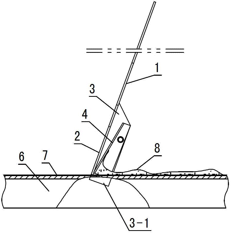
[0016] Such as figure 1 , 2 In the shown embodiment, the main body of this special tool is composed of a handle 1 and a scraper 2 connected to the bottom end of the handle. One side of the scraper 2 is provided with a baffle 3 perpendicular to the scraper. The width of the bottom end 2-1 of the scraper is equal to that of the rubber layer width.

[0017] The baffle 3 is provided with a protrusion 3-1 relative to the bottom end 2-1 of the scraper.

[0018] The baffle plate 3 is provided with a glue return plate 4 with a width of 1 / 4 to 1 / 3 of the width of the bottom end of the scraper 2-1 on the side corresponding to the scraper 2, and the bottom end of the glue return plate is connected to the bottom end of the scraper. There is an angle f of 15--30° between the glue return plate and the scraper surface.

[0019] The glue return plate 4 of the embodiment is provided with a flange 4-1 jo...


PUM


Abstract

The invention relates to a special tool for coating a face gluing layer on a stretching net of a surface mount technology (SMT) laser template. The special tool is characterized in that a main body is formed by a handle and a scraper plate connected with the bottom end of the handle. The width of the bottom end of the scraper plate is equal to the width of the face gluing layer, a baffle is arranged on one side of the scraper plate and is provided with a protruding portion protruding relative to the bottom end of the scraper plate, a glue liquid backflow plate is arranged on one side of the baffle corresponding to the scraper plate, and the width of the glue liquid backflow plate is 1 / 4-1 / 3 of that of the bottom end of the scraper plate. The bottom end of the glue liquid backflow plate is connected with the bottom end of the scraper plate, and an included angle of 15-30 degrees is formed between the glue liquid backflow plate and the plate face of the scraper plate. The baffle and the protruding portion of the special tool enable the scraper plate to be located at the position of the gauze face gluing layer, and the width of the bottom end of the scraper plate is the width of the face gluing layer, so that the width of the face gluing layer formed by the tool is consistent. The glue liquid backflow plate enables glue liquid gathering at the bottom end of the scraper plate to flow to the upper portion of the scraper plate along the surface and then flow back to a glue feeding area to enable the thickness of the face gluing layer to be consistent. The special tool has the advantages of removing working procedures of manual bonding of beautiful line adhesive tapes and remarkably improving production efficiency.

Description

technical field [0001] The invention belongs to the manufacture of SMT laser templates, in particular to a special tool for SMT laser template stretching and coating surface adhesive layers. Background technique [0002] The net yarn and the net frame in the tense state of the SMT laser template are glued and fixed with resin glue, and the adhesive fixation is realized by the primer layer coated on the net frame and the top glue layer coated on the peripheral surface of the net yarn. [0003] In the existing process of coating the surface adhesive layer, in order to prevent the resin glue from sticking to the non-adhesive area of ​​the mesh and the side of the screen frame, it is necessary to manually paste masking tape on the edge of the non-adhesive area of ​​​​the mesh and the side of the screen frame. Peel off the masking tape after the adhesive layer is applied. [0004] The above-mentioned surface adhesive layer coating process has the following obvious defects: 1) Pa...

Claims


Application Information

Patent Timeline
IPC IPC(8): B05C1/06B05C11/02B05C11/10
Inventor 王祖政
Owner 天津光韵达光电科技有限公司
Learn More