
Indoor fire-fighting automatic fire extinguishment system

An automatic fire extinguishing system and fire-fighting technology, which is applied in fire rescue and other directions, can solve the problems of messy indoor wiring, long construction period, and delayed firefighting opportunities, so as to reduce the probability of major accidents, shorten the construction period, and improve the fire-extinguishing efficiency.

Inactive Publication Date: 2017-07-07
CHONGQING UNIVERSITY OF SCIENCE AND TECHNOLOGY
View PDF6 Cites 1 Cited by
  • Summary
  • Abstract
  • Description
  • Claims
  • Application Information

AI Technical Summary

Problems solved by technology

In the layout of the indoor fire protection system of this type of structure, the smoke sensor is generally installed in the corner of the room, and the smoke usually diffuses from the middle position to the two sides; when a fire occurs, such a situation may occur--- During a fire, the smoke spreads indoors, and the smoke sensor has to wait for a long time to detect the smoke and reach a certain concentration before giving an alarm, and the sprinkler device will work to extinguish the fire. In this way, it is likely to delay the chance of fire fighting , resulting in huge losses
At the same time, the smoke sensor needs to be wired separately, which makes the indoor wiring messy and causes a long construction period during the house construction, and the labor cost of the installation and construction unit is high
In the same indoor area, multiple sets of smoke sensors and sprinklers are generally installed, and multiple sets of sprinklers are connected to the water supply network. When a fire occurs, the water supply of each sprinkler will be uneven, and some sprinklers cannot reach the design water supply pressure. , leading to low fire extinguishing efficiency, which may cause major accidents

Method used


Image

  • Indoor fire-fighting automatic fire extinguishment system
  • Indoor fire-fighting automatic fire extinguishment system

Examples


Embodiment Construction

[0010] Below in conjunction with accompanying drawing and embodiment the present invention will be further described:

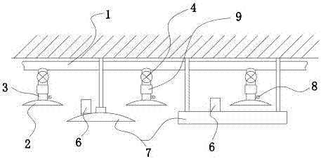
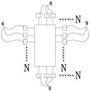
[0011] See attached figure 1 and 2 , the indoor automatic fire extinguishing system for fire protection in the figure includes a plurality of sprinkler devices 2 communicated with the water supply pipe network 1, the sprinkler devices 2 communicate with the water supply pipe network 1 through the connecting pipe 3, and the electromagnetic devices installed on the connecting pipe 3 The valve 4 is connected with the background central processing unit 5 with the PLC control sheet located in the control room, and the electromagnetic valve 4 is controlled to open and close by the background central processing unit 5 with the PLC control sheet, and is connected with the background central processing unit with the PLC control sheet. A plurality of smoke sensors 6 connected to the device 5; wherein: the smoke sensor 6 is fixed on the shell of the fluorescent lamp 7 ...


PUM


Abstract

The invention relates to an indoor fire-fighting system, in particular to an indoor fire-fighting automatic fire extinguishment system. The indoor fire-fighting automatic fire extinguishment system comprises a plurality of spraying devices communicating with a water supply network, and a plurality of smoke transducers; the spraying devices communicate with the water supply network through connection pipes; electromagnetic valves installed on the connection pipes are connected with a background central processor located in a control chamber and provided with an PLC control chip; the electromagnetic valves are controlled by the background central processor provided with the PLC control chip to open and close; the smoke transducers are connected with the background central processor provided with the PLC control chip and fixed on fluorescent lamp shells located in the indoor using area; and data lines of the smoke transducers and electric power conductors of fluorescent lamps are located in the same wiring channel. The indoor fire-fighting automatic fire extinguishment system shortens the construction period, reduces the construction cost, can rapidly start the spraying devices in time, improves the fire extinguishment efficiency and reduces probability of occurrence of major accidents.

Description

technical field [0001] The invention relates to an indoor fire-fighting system, in particular to an indoor fire-fighting automatic fire-extinguishing system which shortens the construction period, reduces the construction cost, starts the spraying device quickly and in time, improves the fire-extinguishing efficiency and reduces the probability of major accidents. Background technique [0002] In some indoor areas such as underground garages, logistics warehouses, shopping malls, schools, hospitals, etc., indoor fire protection systems are required to be built during housing construction to ensure the safety of people's lives and property. [0003] The indoor fire protection system of the existing structure generally includes a smoke alarm connected to the background central processing unit, a sprinkler device connected to the water supply pipe network, and a solenoid valve for controlling the opening and closing of the spraying device. The opening and closing are controlled...

Claims


Application Information

Patent Timeline
Patent Type & Authority Applications(China)
IPC IPC(8): A62C31/05A62C37/44
CPCA62C31/05A62C37/44
Inventor 陈国荣刘松李忠杜晓霞罗建伟邓菊丽冯骊骁利节陈承源祝华正胡刚葛继科赖军辉任虹
Owner CHONGQING UNIVERSITY OF SCIENCE AND TECHNOLOGY
Learn More